Ntp message format – H3C Technologies H3C SR8800 User Manual
Page 65
53
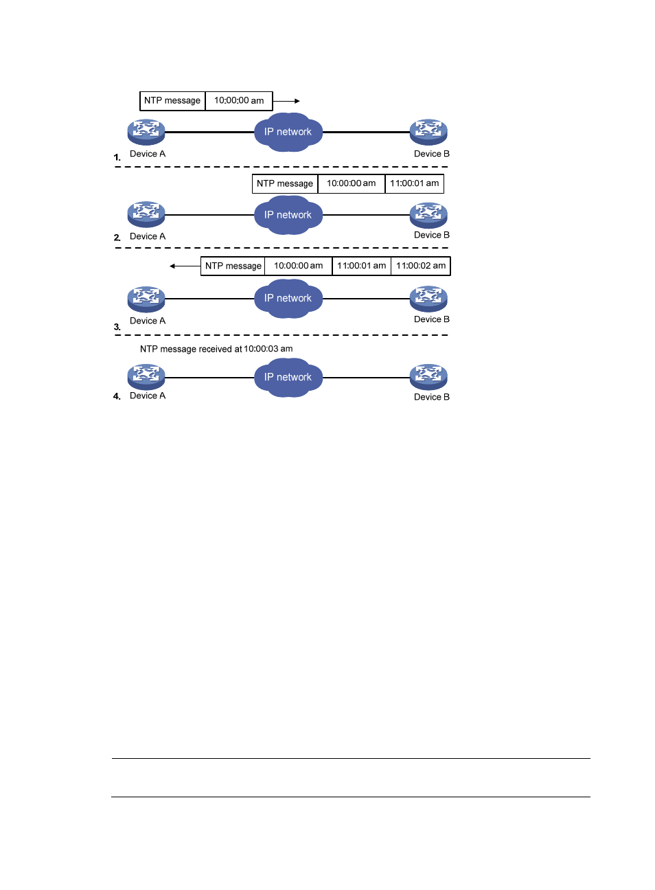
Figure 19 Basic work flow of NTP
The process of system clock synchronization is as follows:
•
Device A sends Device B an NTP message, which is timestamped when it leaves Device A. The time
stamp is 10:00:00 am (T1).
•
When this NTP message arrives at Device B, it is timestamped by Device B. The timestamp is
11:00:01 am (T2).
•
When the NTP message leaves Device B, Device B timestamps it. The timestamp is 11:00:02 am
(T3).
•
When Device A receives the NTP message, the local time of Device A is 10:00:03 am (T4).
Up to now, Device A has sufficient information to calculate the following two important parameters:
•
The roundtrip delay of NTP message: Delay = (T4–T1) – (T3-T2) = 2 seconds.
•
Time difference between Device A and Device B: Offset = ((T2-T1) + (T3-T4))/2 = 1 hour.
Based on these parameters, Device A can synchronize its own clock to the clock of Device B.
This is only a rough description of the work mechanism of NTP. For details, refer to RFC 1305.
NTP message format
NTP uses two types of messages, clock synchronization message and NTP control message. An NTP
control message is used in environments where network management is needed. As it is not a must for
clock synchronization, it will not be discussed in this document.
NOTE:
All NTP messages mentioned in this document refer to NTP clock synchronization messages.