Configuration procedure – H3C Technologies H3C SR8800 User Manual
Page 86
74
•
Router D and Router A work in the multicast client mode and receive multicast messages through
their respective GigabitEthernet 3/1/10.
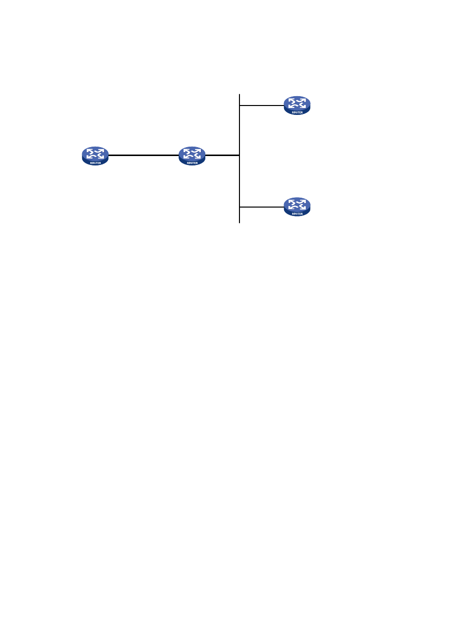
Figure 28 Network diagram
Configuration procedure
1.
Set the IP address for each interface as shown in
. (Details not shown)
2.
Configure Router C:
# Specify the local clock as the reference source, with the stratum level of 2.
<RouterC> system-view
[RouterC] ntp-service refclock-master 2
# Configure Router C to work in the multicast server mode and send multicast messages through
GigabitEthernet 3/1/10.
[RouterC] interface GigabitEthernet 3/1/10
[RouterC-GigabitEthernet3/1/10] ntp-service multicast-server
3.
Configure Router D:
# Configure Router D to work in the multicast client mode and receive multicast messages on
GigabitEthernet 3/1/10.
<RouterD> system-view
[RouterD] interface GigabitEthernet 3/1/10
[RouterD-GigabitEthernet3/1/10] ntp-service multicast-client
Because Router D and Router C are on the same subnet, Router D can receive the multicast
messages from Router C without being IGMP-enabled and can be synchronized to Router C.
# View the NTP status of Router D after clock synchronization.
[RouterD] display ntp-service status
Clock status: synchronized
Clock stratum: 3
Reference clock ID: 3.0.1.31
Nominal frequency: 64.0000 Hz
Actual frequency: 64.0000 Hz
Clock precision: 2^7
Clock offset: 0.0000 ms
Root delay: 31.00 ms
Root dispersion: 8.31 ms
GE3/1/1
1.0.1.10/24
Router A
GE3/1/10
3.0.1.31/24
GE3/1/10
3.0.1.32/24
Router B
Router C
Router D
GE3/1/10
1.0.1.11/24
GE3/1/10
3.0.1.30/24