Page – RISCO Group Gardtec GT600 User Manual
Page 110
Page
108
GT 600 / 601 Engineer’s Reference Guide
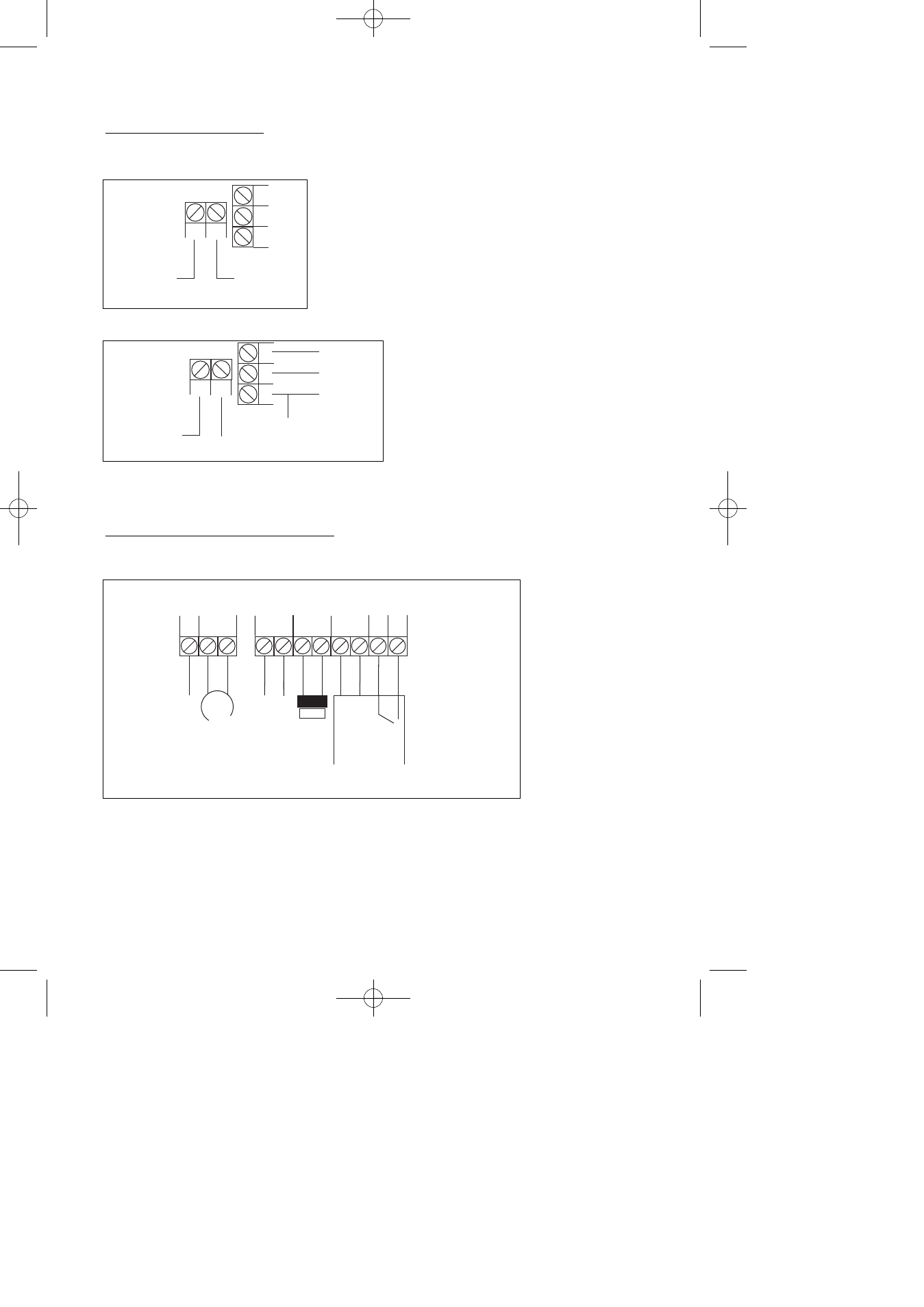
Telephone Connections
Fig 3.
Fig 4.
Control Panel Output Connections
Fig 5.
A5
IN
B2
IN
C3
B2
A5
Terminal 5
(on existing BT socket)
OR
Terminal A
(on BT Terminal Block)
Terminal 2
(on existing BT socket)
OR
Terminal B
(on BT Terminal Block)
A5
IN
B2
IN
C3
B2
A5
Terminal 5
(on existing BT Master socket)
Terminal 2
(on existing BT Master socket)
Terminal 3
(on exist ng BT Master socket)
Terminal 5
(on other extension sockets)
Terminal 2
(on other extension sockets)
Terminal 3
(on other extension sockets)
Serial
Telephone
Connection
(depending on model)
Standard
Telephone
Connection
PGM1
SPKR
+
-
A
UX 12V
+
-
+
-
+
-
STR
OBE
BELL
BELL HOLD
-
SAB T
AMP
Supply f
or Detectors
RKPs Etc
Strobe
Light
Sounder/SAB Unit
Speaker
Prog
rammab
le ter
minal f
or
latching detectors etc.
12V Trig
0V
Tamp
Ret
16 Ohm
Min
Terminal positions may differ.