Page – RISCO Group Gardtec GT600 User Manual
Page 113
Page
111
GT 600 / 601 Engineer’s Reference Guide
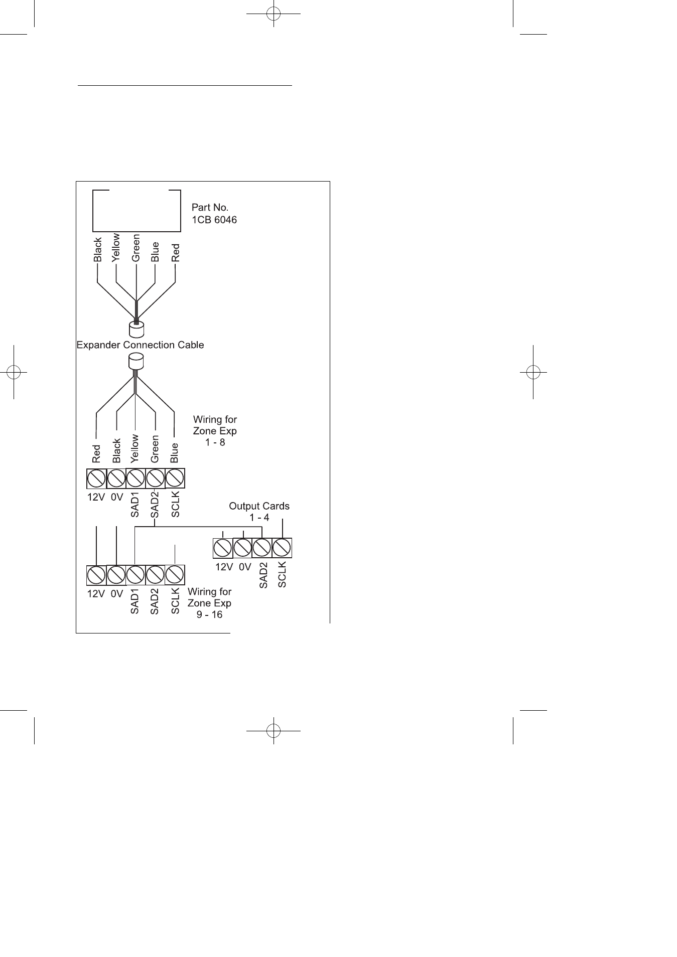
Zone/Output/ID Expander Card Connections
Upto 4 zone expander cards (or 1 ID Expander card) can be fitted to the 600. Up to 16
zone expander cards (or 2 ID Expander card) can be fitted to the 601. These are all fit-
ted to a common expander bus via a serial connection lead (part No. 1CB 6046). This
lead is fitted to the plug on the front of the control panel PCB and the cards wired as
shown below. Refer to page 112 for ID compatibility and output cards.
Fig 11.
Notes:
Remove power from panel
before connecting Expander
Cards.
Zone Expansion Types (ZEX
or ID) are programmed via
option 72
Zone Expander Cards are pro-
grammed via options 75 & 76.
Ensure ident jumper on Zone
Expander is in position 1 to 4
as required.
Zones numbers on Expander
No.1 start at 21(e.g AZ1 on
expander 1 = zone 21).
Zones numbers on Expander
No.2 start at 31(e.g AZ1 on
expander 2 = zone 31).
Zones numbers on Expander
No.3 start at 41(e.g AZ1 on
expander 3 = zone 41).
Zones numbers on Expander
No.4 start at 51(e.g AZ1 on
expander 4 = zone 51).
If ID zones are used the first
zone on the ID card is Zone 21
For Output Expanders ensure
ident jumper is in required posi-
tion (1 - 4).
Output Expanders are pro-
grammed via option 83 and
may be programmed only via a
LCD RKP.
To Other Expanders
600 / 601 PCB
For ZEX 9, jumper should be on Address 1 and
ZEX 16, jumper should be on Address 8