2 connector wiring, 6 dvd-rw installation, 1 video-in/out connections – Rugged Cams HD Megapixel User Manual
Page 24: 2 monitor connections (video out, vga and spot), 3 hdmi connections (c, d, e, f, g, h and i type)
24
2.1.6 DVD-RW
installation
Securely fix DVD-RW by using bracket and screws provided herewith.
Please do not use any different DVD-RW cables (data cable and power supply cable) other than the ones we provide.
Otherwise, it may cause damage to the DVD-RW.
Only one DVD-RW can be used. Mount it at the SATA 3 port. (A and C Type) or SATA 4 port (B, D, E, F, G, H and I type)
CAUTION
Install DVD-RW hard disk after DVR power off. Otherwise, it may cause permanent damage to the hard disk. To turn off DVR, please click (
)
SETUP>SYSTEM>Shutdown. Also, wait for 5 seconds before plugging in power supply again.
2.2 Connector Wiring
2.2.1 Video-In/Out
Connections
A, B, C, D and E Type
Connect a camera to ‘VIDEO IN’.
If user wishes to link camera input to another device, please connect the camera to ‘LOOP OUT’.
Assure the ‘VIDEO IN’ and ‘LOOP OUT’ connections are connected properly, not oppositely.
F, G and H Type
Connect cameras to ‘HD-SDI IN’ to channel 1 to 16.
I Type
Connect cameras to ‘HD-SDI IN’ to channel 1 and 2.
Connect cameras to ‘VIDEO IN’ to channel 3 to 16.
If user wishes to link camera input to another device, please connect the camera to ‘LOOP OUT’
Assure the ‘VIDEO IN’ and ‘LOOP OUT’ connections are connected properly, not oppositely.
(NOTE)
Only B, D, E, and I Type model supports LOOP OUT connection.
2.2.2 Monitor Connections (Video Out, VGA and Spot)
Use with CCTV monitor and computer monitor. Please connect the CCTV monitor to ‘VIDEO OUT’(except for G and H
Type), the computer monitor to ‘VGA’, respectively. If necessary, connect another CCTV monitor to ‘SPOT’
Multi Spot (C and D Type)
- This function supports Multi Channel Display on Spot Monitor
- Connect BNC cable between spot monitor and multi spot port of rear panel.
2.2.3 HDMI connections (C, D, E, F, G, H and I Type)
Connect HDMI cable to HD out port of rear panel and HDMI port of HD output device.
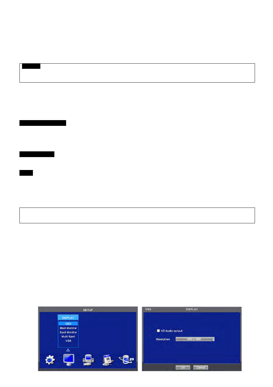
Please click ( ) SETUP> DISPLAY> VGA and the following screen will appear.