Robot mounting procedure – Adept s350 Cobra User Manual
Page 20
Chapter 2: Robot Installation
Robot Mounting Procedure
1. Using the dimensions shown in Figure 2-2, drill and tap the mounting surface for four
M10 x 30 mm (or 3/8-16 UNC) machine bolts (user-supplied). Also drill two 6H7
diameter holes for a diamond-shaped dowel pin and an internally-threaded positioning
pin. See Table 2-2 for bolt and torque specifications.
WARNING: Do not attempt to extend the inner or outer
links of the robot until the robot has been secured in
position. Failure to comply could result in the robot
falling and causing either personnel injury or equipment
damage.
2. Install a diamond-shaped pin into one of the 6H7 diameter holes.
3. Install an internally-threaded positioning pin into the other 6H7 hole.
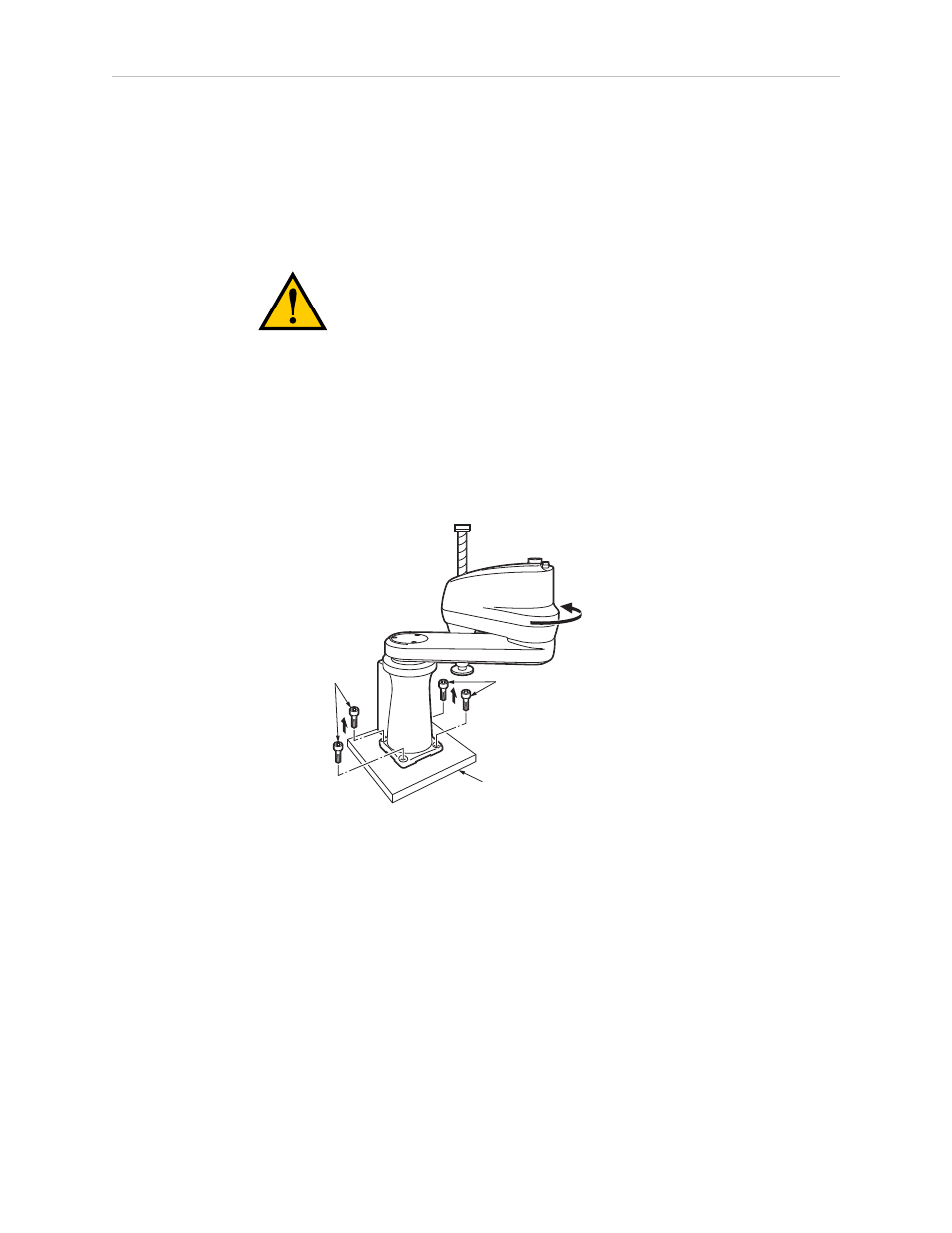
4. Turn the J2 axis until it comes into contact with the mechanical hardstop to keep the
robot in a safe position.
Bolts
Pallet
Bolts
Turn until it comes
into contact with
the mechanical end.
Figure 2-3. Rotate J2 Axis to Safe Position
5. Remove the four bolts securing the robot base to the pallet. One person should support
the J1 axis arm while another person removes the bolts. Retain these bolts for possible
later relocation of the equipment.
6. Lift the robot and position it directly over the mounting surface.
7. Slowly lower the robot while aligning the base and the tapped mounting holes in the
mounting surface.
NOTE: The base casting of the robot is aluminum and can easily be dented if
bumped against a harder surface. Verify that the robot is mounted squarely (will
not rock back and forth) before tightening the mounting bolts.
Adept Cobra s350 User's Guide, Rev. D
Page 20 of 94