User electrical lines – Adept s350 Cobra User Manual
Page 59
Chapter 6: Optional Equipment Installation
1 2 3 4
16 17 18 19
5 6 7 8 9
10 11 12 13 14 15
Brake release
swtch
Air piping joints
(M5)
CN21 pin layout
(A)
View in direction of arrow (B)
CN20 pin layout
AIR 1,2
Ø
4, BSPT 1/8
AIR 3,4
Ø
6, BSPT 1/4
0.59 MPa
View in direction of arrow (A)
(B)
Air piping
joint
Maximum
allowable pressure
Air No.
AIR1 and AIR2
AIR3 and AIR4
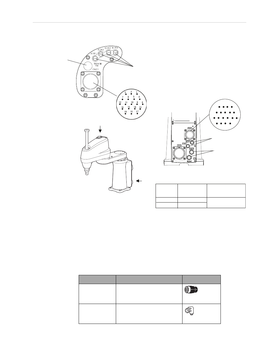
Figure 6-2. User Air and Electrical Connectors on Robot
User Electrical Lines
There are 19 user electrical lines that run from CN20 at the back of the robot, up to CN21 on
the top of Joint 2, as shown in the previous figure. Maximum current per line is 1 Amp. Use
the supplied mating connector sets, shown in the following table, for CN20 and CN21.
Table 6-1. Mating Connectors for CN20 and CN21
Connector No.
Model and part name
Appearance
for CN20
SRCN6A25-24S (round type
connector) Japan Aviation
Electronics Industry Ltd.
for CN21
JMLP2119M (L type plug
connector) DDK Electronics,
Inc.
Adept Cobra s350 User's Guide, Rev. D
Page 59 of 94