Reinstalling the flange, 3 user connections on robot, User air lines – Adept s350 Cobra User Manual
Page 58
Chapter 6: Optional Equipment Installation
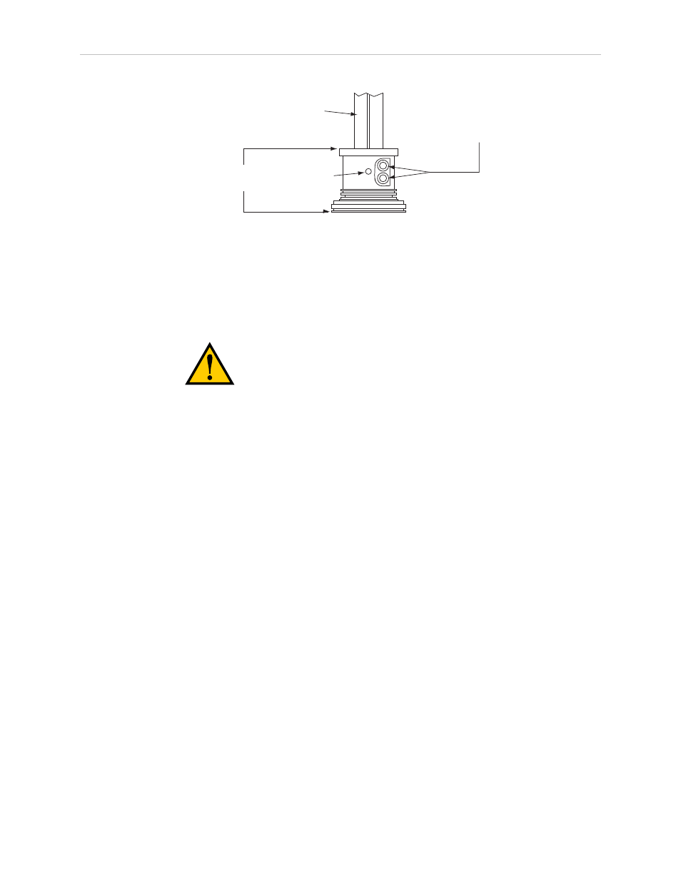
Tool flange
assembly
Setscrew
M4 Socket-Head
Cap screws
Quill shaft
Figure 6-1. Tool Flange Removal Details
Reinstalling the Flange
1. Slide the flange up on the quill shaft as far as it will go, and rotate it until the setscrew
is lined up with the flat section on the quill shaft.
CAUTION: The setscrew must align with the flat section
of the shaft or damage to the quill will result.
2. Support the flange while using a 2.5 mm hex driver to tighten the setscrew to finger
tightness. Do not over-tighten the setscrew because this will cause the flange to be off-
center from the quill shaft.
3. Tighten one of the M4 screws part of the way, then tighten the other one the same
amount. Alternate between the two screws so there is even pressure on both when they
are tight. The torque specification for each screw is 8 N·m (70 in-lb).
6.3 User Connections on Robot
User Air Lines
There are four user air line connectors on the robot user panel on the back of the robot (see
Figure 6-2). The four air lines run through the robot up to another set of four matching
connectors on the top of the outer link. The maximum pressure for the air source is 0.59 MPa
(86 psi). The Adept Cobra s350 is not equipped with solenoid valves.
Adept Cobra s350 User's Guide, Rev. D
Page 58 of 94