Comtech EF Data SDM-100A User Manual
Page 118
Theory of Operation
SDM-100A Satellite Modem
4–2
Rev.
0
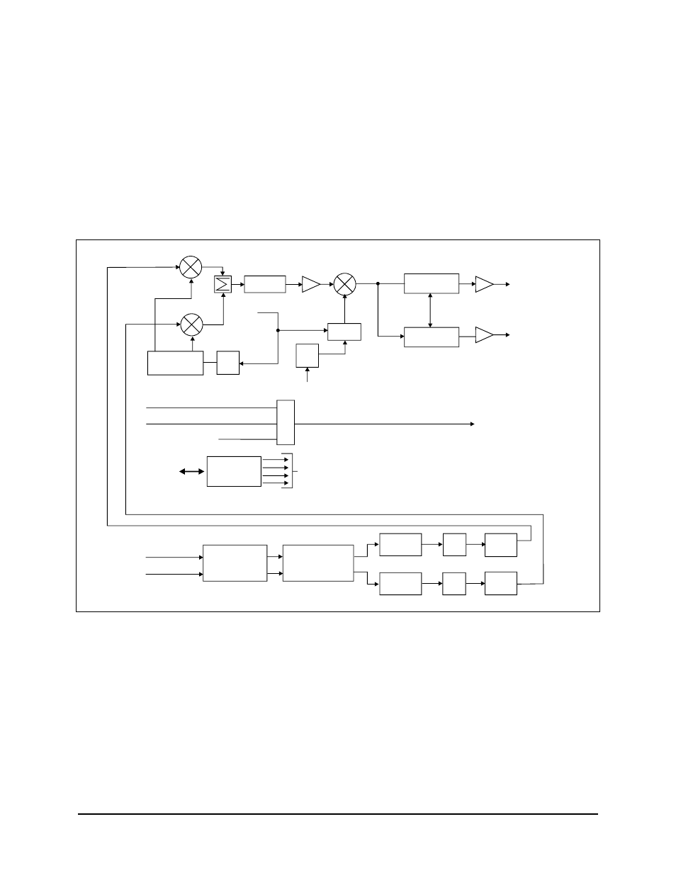
Fault information from the modulator is sent to the host M&C, and includes:
• Synthesizers
out-of-lock
• RF output leveled
• Input data clock activity
• I channel digital filter activity
• Q channel digital filter activity
• AGC level faults
VCO
DDS
REF
OSC
MPC
MPC
IF OUTPUT
50 TO 180 MHz
-5 TO -30 dBm
MPC
IMPC
MPC
MPC
MPC
I
Q
M&C
COMMAND
BUS
MICRO-
PROCESSOR
SCT
IF LOOPBACK
RX SAT CLK
EXT. CLOCK
TX_DATA
TX_CLOCK
SCRAMBLERS
AND
DIFFERENTIAL
ENCODER
CONVOLUTIONAL
ENCODERS
DIGITAL
NYQUIST
DAC
ALIAS
FILTER
DIGITAL
NYQUIST
DAC
ALIAS
FILTER
0
90
IF FILTER
VARIABLE
ATTENUATOR
ATTENUATOR
RF
SYNTH
Figure 4-1. Modulator Block Diagram
Data to be transmitted will come from the interface card, via the demodulator. The format
is RS-422, and includes a clock synchronous with the data. The data signal at this point is
clean and free of jitter.
The data signal then goes to the scrambler (which provides energy dispersal) and then to
the differential encoder. The differential encoder is a 2-bit encoder, which allows for
resolution of two of the four ambiguity states of the QPSK demodulator.