4 test points, 1 demodulator/m&c/interface test points – Comtech EF Data SDM-100A User Manual
Page 148
Maintenance
SDM-100A Satellite Modem
5–6
Rev.
0
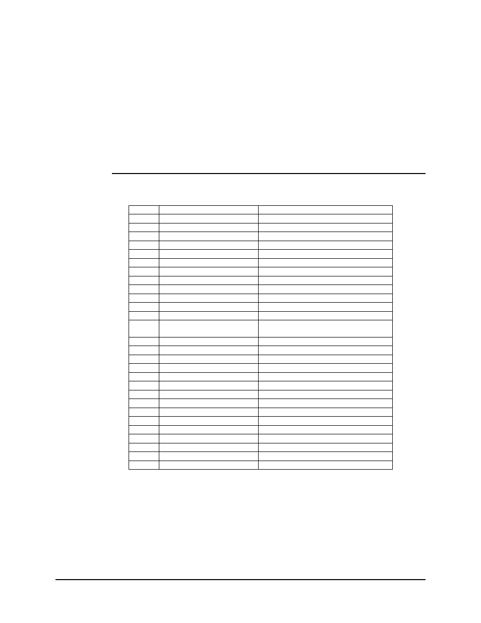
5.1.4 Test Points
The modem does not have accessible test points. When troubleshooting is required at
board level, the cover must be removed.
The following is a list of test points located on the PCB, and a description of the signal
that is to be present under normal operation.
5.1.4.1 Demodulator/M&C/Interface Test Points
TP 41
SYMBCK
Symbol Clock
TP 37
DP1
Constellation I Test Point
TP 38
DP2
Constellation Q Test Point
TP 29
GND
Ground
TP 34
DATCLK
Data Rate Clock
TP 4
GND
Ground
TP 3
+5V
Plus 5 Volt
TP 12
SD
Send Data
TP 13
TT
Terminal Timing (Transmit Clock)
TP 14
RD
Receive Data
TP 15
RT
Receive Timing
TP 16
GND
Ground
TP 11
GND
Ground
TP 31
IF SYNTH REF
(R143 must be populated)
IF Synthesizer Reference
TP 36
RX CLK
Buffer Output Clock
TP 28
AGC CNRL
Digital AGC control
TP 26
AGC DRV
Analog AGC drive
TP 18
I
I channel Analog RF Output
TP 19
Q
Q channel Analog RF Output
TP 25
GND
Ground
TP 20
Q OFF
Analog Q channel DC offset control
TP 24
I OFF
Analog I channel DC offset control
TP 21
Q CHAN
Q channel Analog anti-alias filter output
TP 22
I CHAN
I channel Analog anti-alias filter output
TP 27
Q A/D IN
Q channel Analog to Digital input
TP 30
I A/D IN
I channel Analog to Digital input
D9
OVFL
Buffer Overflow LED
D10
UNFL
Buffer Underflow LED
D11 XDN/PG
XILINX
Done Programming LED