B.3.2 reed-solomon decoder – Comtech EF Data SDM-100A User Manual
Page 204
Options
SDM-100A Satellite Modem
B–22
Rev.
0
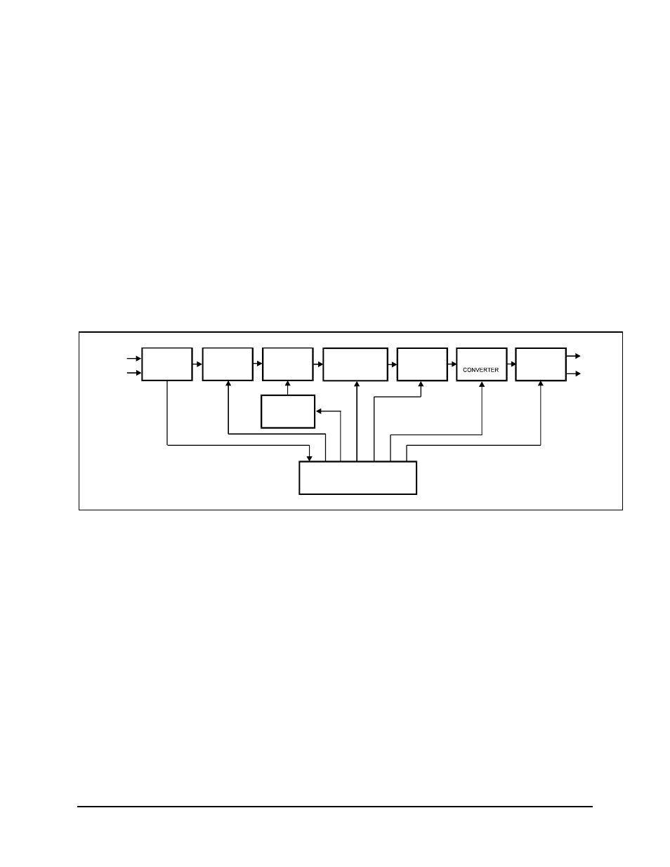
B.3.2 Reed-Solomon Decoder
Refer to Figure B-7 for a block diagram of the Reed-Solomon decoder section.
The Reed-Solomon decoder section includes the following circuits:
• Serial/Parallel
Converter
• Synchronous
FIFO
• RAM
Interleaver
• Parallel/Serial
Converter
• Reed-Solomon
Encoder/Decoder
• Synchronous
Descrambler
DMXDAT
(SERIAL)
JP2
PARALLEL
SYNCHRONOUS
SYNCHRONOUS
RS
SERIAL
RAM
UNIQUE WORD
RXSATDAT
(SERIAL)
JP2
RXSATCLK
JP2
DETECTOR
U10
CONVERTER
PARALLEL
TO
U10
U11
DEINTERLEAVER
CODEC
(DECODER SECTION)
U2
DEINTERLEAVER
U12
U10
FIFO
DESCRAMBLER
TO SERIAL
U10
DMXCLK
JP2
ADDRESS
GENERATOR
U10
RS TIMING CONTROLLER
U10
Figure B-7. Reed-Solomon Decoder Section Block Diagram
The data and the clock signals come from the demultiplexer on the interface PCB, and are
sent to the Reed-Solomon decoder section through connector JP2.
The data is sent through a serial/parallel converter. Because it was block-interleaved by
the encoder, the data must pass through a de-interleaver with the same depth as the
interleaver used on the encoder. The de-interleaver is synchronized by the detection of
the unique words, which are placed at the end of each page by the interleaver on the
encoder.
Once the de-interleaver is synchronized to the incoming data, the data is reassembled into
its original sequence, in accordance with the INTELSAT-308 Rev. 6B specification. The
data is then sent to the Reed-Solomon outer decoder.