4 external connections – Comtech EF Data SDM-100A User Manual
Page 31
SDM-100A Satellite Modem
Installation
Rev. 0
2–5
2.4 External Connections
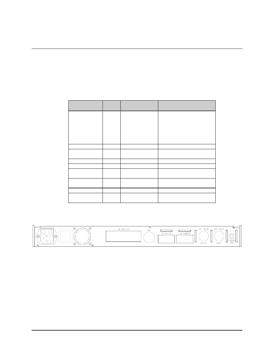
Connections between the modem and other equipment are made through five connectors.
These connectors are listed in Table 2-1, and their locations are shown in Figure 2-2.
The use of each connector is described in the following paragraphs.
Table 2-1. Rear Panel Connectors
Name
Ref.
Desig.
Connector
Type
Function
DATA I/O
J8
Various:
Data Input/Output:
37-pin
D
RS-422/449
34-pin block or
25-pin D
V.35
25-pin
D
RS-232
50-pin
D
ASYNC
50-pin D
ADPCM Voice
REMOTE
J6
9-pin D
Remote Interface
FAULTS
J7
9-pin D
FORM-C Fault Relay
Contacts
TX/IF OUTPUT
CP1
BNC
TX IF Output
RX/IF INPUT
CP2
BNC
RX IF Input
AC POWER
None
Standard
Alternating Current (AC)
Power Input
DC POWER
None
Terminal block
Direct Current (DC)
Power Input
CHASSIS GND
GND
#10-32 stud
Chassis Ground
AGC
AGC
Test point
Automatic Gain Control (AGC)
Test Point
Figure 2-2. Rear Panel View