Comtech EF Data SDM-100A User Manual
Page 202
Options
SDM-100A Satellite Modem
B–20
Rev.
0
TXSATDAT
JP2
PARALLEL
RAM
UNIQUE WORD
RS
SERIAL
SYNCHRONOUS
SYNCHRONOUS
MUXDATA
(SERIAL)
JP2
MUXCLK
JP2
SCRAMBLER
U3
CONVERTER
PARALLEL
TO
U3
U6
FIFO
CODEC
(ENCODER SECTION)
INSERTION
U2
INTERLEAVER
U3
U4
INTERLEAVER
TO SERIAL
U3
TXSATCLK
JP2
ADDRESS
GENERATOR
U3
RS TIMING CONTROLLER
U3
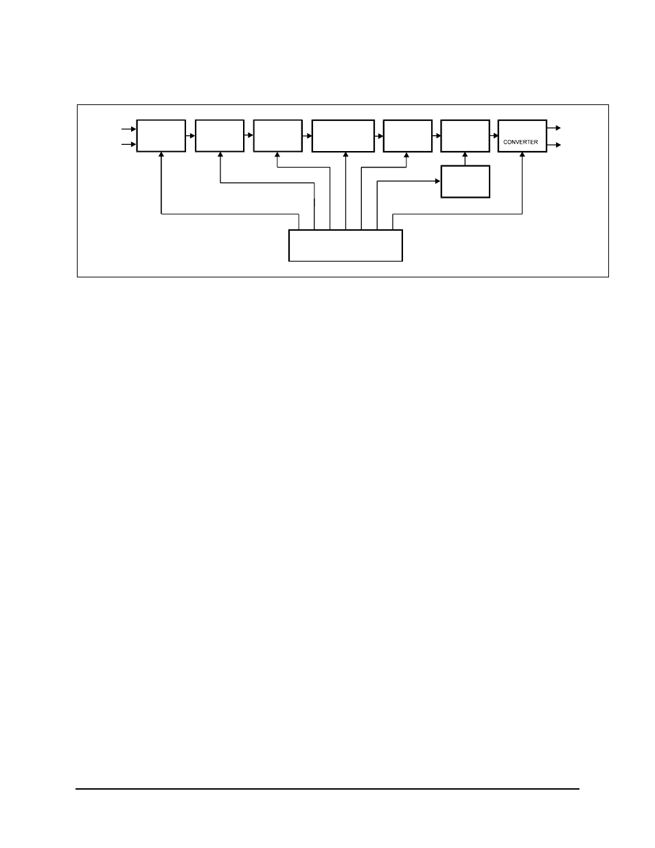
Figure B-5. Reed-Solomon Encoder Section Block Diagram
The data and clock signals (MUXDATA and MUXCLK) come from the multiplexer on
the interface PCB, and are sent to the Reed-Solomon encoder section through connector
JP2. Since the data input to the Reed-Solomon encoder is serial, the data passes through a
self-synchronizing serial scrambler, in accordance with specification INTELSAT-308,
Rev. 6B.
The host software allows the scrambler to be turned on or off at the front panel, as
required by the user. If the scrambler is disabled, the data passes through the scrambler
unaltered.
The data then passes through a serial/parallel converter, which changes the data to an 8-
bit word. The word then passes to a synchronous First In/First Out (FIFO) buffer,
because the rate is different than the encoded data rate. Once buffered by the FIFO, the
data passes to the Reed-Solomon Codec.
Refer to Figure B-6 for the Reed-Solomon code page format. The Reed-Solomon outer
Codec reads the data in blocks of n bytes, and calculates and appends check bytes to the
end data block. The letter k represents the total number of bytes in a given block of data
out of the Codec. The letter n represents the number of data bytes in a given block.
The term, k - n = 2t, is the total number of check bytes appended to the end of the data.
This is referred to as the “Reed-Solomon overhead.” The terms k, n, and t will vary,
depending on the data rate used. The output data is passed to a block-interleaver.