1 connector pinouts – Comtech EF Data SDM-100A User Manual
Page 133
SDM-100A Satellite Modem
Theory of Operation
Rev. 0
4–17
Fault indicators are also provided on TTL open collector drivers on the RS-422
connector.
• The TTL MOD fault indicates one of the following:
MODULATOR
fault
COMMON EQUIPMENT fault
• The TTL DEMOD fault indicates one of the following:
DEMOD
fault
COMMON EQUIPMENT fault
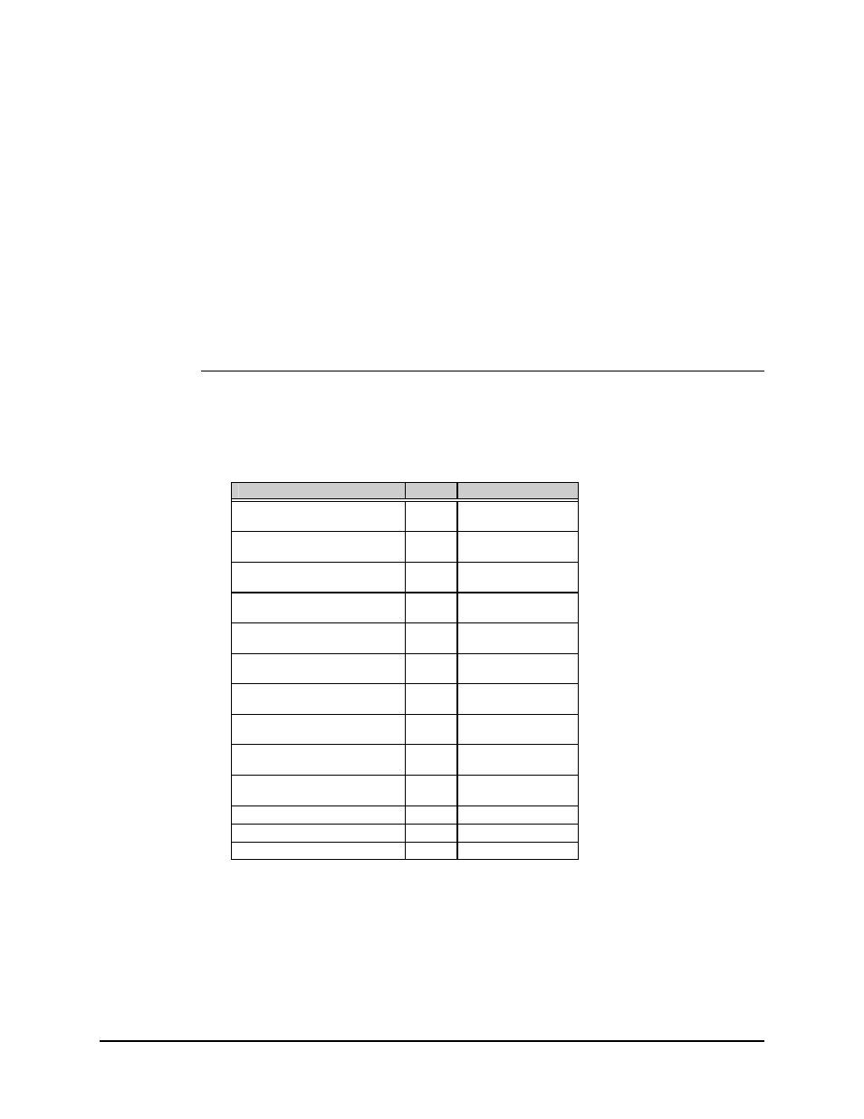
4.4.1.1 Connector Pinouts
The RS-422 interface is provided on a 37-pin female D connector accessible from the
rear panel of the modem. Screw locks are provided for mechanical security of the mating
connector.
Signal Function
Name
Pin #
Send Data
SD-A
4
SD-B
22
Send Timing
ST-A
5
ST-B
23
Receive Data
RD-A
6
RD-B
24
Request To Send
RS-A
7
(See note below)
RS-B
25
(See note below)
Receiver Timing
RT-A
8
RT-B
26
Clear To Send
CS-A
9
(See note below)
CS-B
27
(See note below)
Data Mode
DM-A
11
DM-B
29
Receiver Ready
RR-A
13
RR-B
31
Terminal Timing
TT-A
17
TT-B
35
Master Clock (Input)
MC-A
16
MC-B
34
Demod Fault
—
21
Mod Fault
—
3
Signal Ground
SG
1, 19, 20, 37
Note: The Request to Send (RTS) line is hard-wired to the Clear to Send (CTS) line
by JP11, pins 5 and 6, on the Demodulator/M&C card (AS/4973), since the modem
does not support polled operation.