2 connector pinouts – Comtech EF Data SDM-100A User Manual
Page 141
SDM-100A Satellite Modem
Theory of Operation
Rev. 0
4–25
Two fault outputs are provided on dry contact Form-C relays on the Demodulator/M&C
card, and are sent to the interface card. The signals are buffered and output for use in
monitoring fault status, and are available on the FAULT connector on the modem rear
panel. These are:
• MODULATOR
faults
• DEMODULATOR
faults
Generation of these fault conditions is described in Chapter 3.
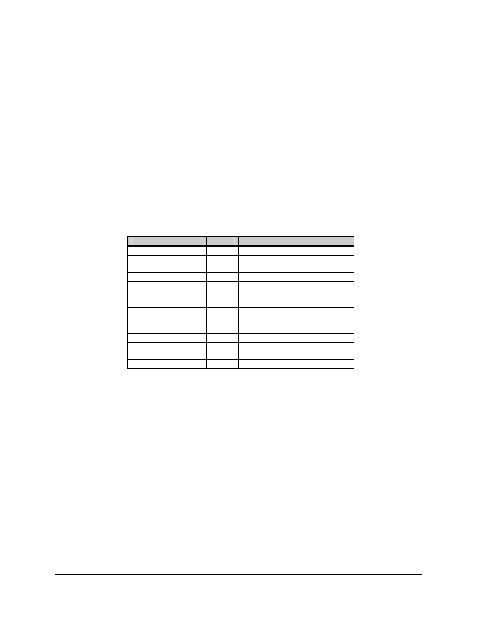
4.4.3.2 Connector Pinouts
The RS-232-C interface is provided on a 25-pin D female connector (DCE) accessible
from the rear panel of the modem. Screw locks are provided for mechanical security of
the mating connector.
Signal Function
Name
Pin #
Ground GND
1,
7
Send Data
SD
2
Receive Data
RD
3
Request To Send
RTS
4
(See note below)
Clear To Send
CTS
5
(See note below)
Data Mode
DM
6
Receiver Ready
RR
8
Master Clock
MC
9
Demod Fault
DF
11
Send Timing
ST
15
Receive Timing
RT
17
Terminal Timing
TT
24
Mod Fault
MF
25
No Connection
10, 12, 14, 16, 19, 20, 21, 22, 23
Note: The Request to Send (RTS) line is normally hard-wired to the Clear to Send
(CTS) line by JP11, pins 5 and 6, on the Demodulator/M&C card (AS/4973).