1 connector pinouts – Comtech EF Data SDM-100A User Manual
Page 137
SDM-100A Satellite Modem
Theory of Operation
Rev. 0
4–21
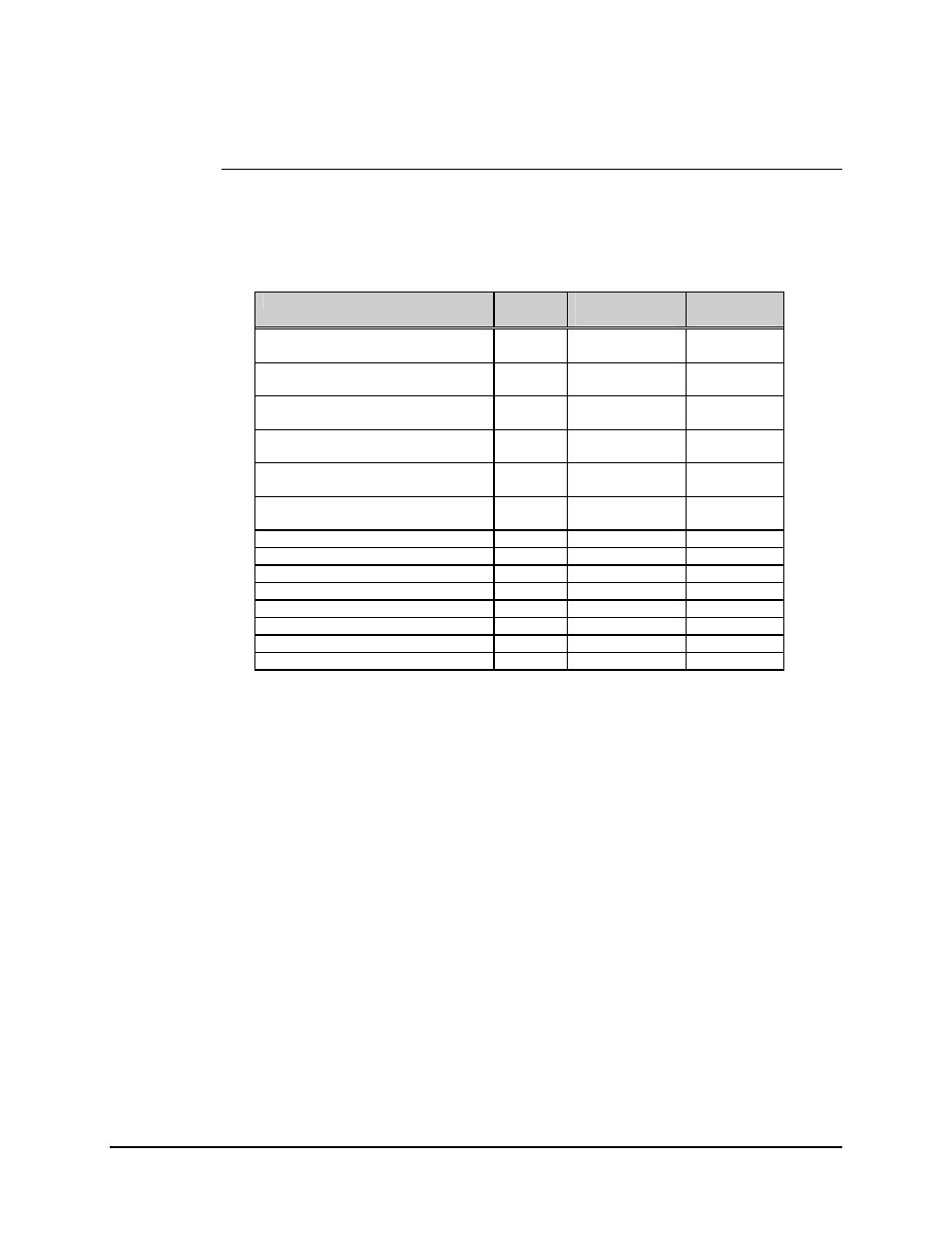
4.4.2.1 Connector Pinouts
The V.35 interface is provided on the industry standard 34-pin block or 25-pin D
connector accessible from the rear panel of the modem. Screw locks are provided for
mechanical security of the mating connector.
Signal Function
Name
34-Pin Block
Pin #
25-Pin ‘D’
Pin #
Send Data
SD-A
P
2
SD-B
S
14
Serial Clock Transmit
SCT-A
Y
15
SCT-B
a
(AA)
12
Receive Data
RD-A
R
3
RD-B
T
16
Serial Clock Receive
SCR-A
V
17
SCR-B
X
9
Serial Clock Transmit External
SCTE-A
U
24
SCTE-B
W
11
Master Clock (Input)
MC-A
c (CC)
20
MC-B
d
(DD)
23
Request To Send
RTS
C
(See note)
4
Clear To Send
CTS
D
(See note )
5
Data Set Ready
DSR
E
6
Receive Line Signal Detect
RLSD
F
8
Modulator Fault
---
m (MM)
25
Demodulator Fault
---
n (NN)
21
Shield Shield
1
Signal Ground
SG
A, B
7
Note: The Request to Send (RTS) line is hard-wired to the Clear to Send (CTS) line
by JP11, pins 5 and 6, on the Demodulator/M&C card (AS/4379), since the modem
does not support polled operation.