Figure 4-4. viterbi decoder block diagram – Comtech EF Data SDM-100A User Manual
Page 124
Theory of Operation
SDM-100A Satellite Modem
4–8
Rev.
0
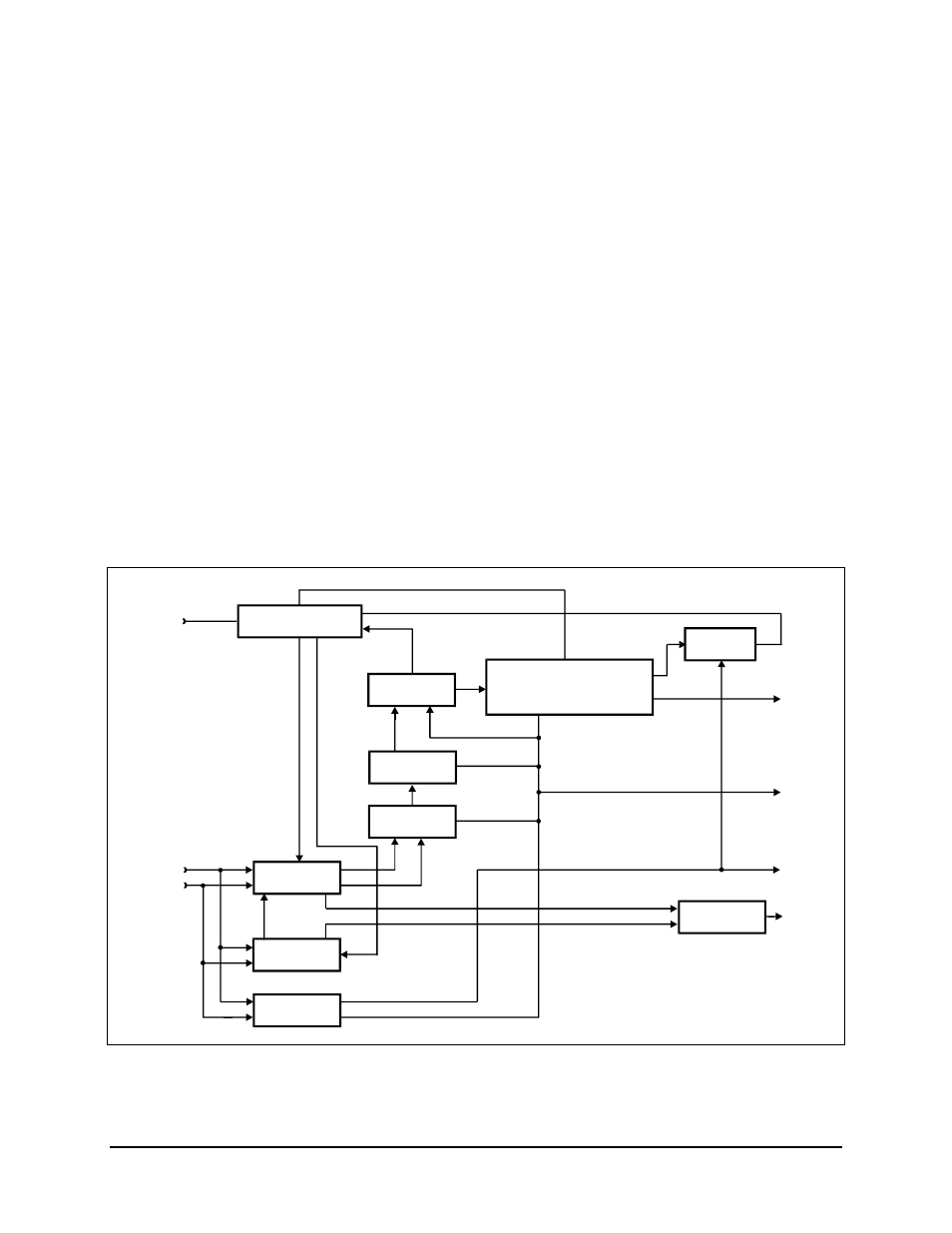
A set of “branch metric” values is then computed for each of the received symbol pairs,
related to the probability that the received symbol pair was actually transmitted as one of
the four possible symbol pairs. The “branch metrics” are then processed by the
Add-Select-Compare (ASC) computer.
The ASC computer makes decisions about the most probable transmitted symbol stream
by processing the current branch metrics with the state metrics computed for the 64
previous decoder inputs. The results of the ASC computer are stored in memory called
“path memory.”
Path memory is 80 states in depth. The path with the maximum metric is designated the
survivor path, and its data is used for output. The difference between the minimum and
maximum path metrics is used as the means of determining decoder synchronization. The
data may then be descrambled and differentially decoded. Both of these processes are
optional and may be selected by the user locally or remotely. The data signal out of the
differential decoder is sent to the interface card for formatting and output.
The synchronization signal is used for Lock Detect and sent to the M&C. The raw BER
count is generated from the minimum and maximum metrics, and sent to the M&C for
further processing.
MICRO-
COMPUTER
BUS
MICROCOMPUTER
INTERFACE
VITERBI DECODER INCLUDING
LOCK
DETECT
RECEIVE
DATA
V.35 DESCRAMBLER AND
CHANNEL BER DETECTION
DEPUNCTURE
PROCESSOR
AMBIGUITY
RESOLVER
INPUT
BUFFER
RECEIVE
CLOCK
AGC
CONTROL
COSTAS
PROCESSOR
I CHANNEL
Q CHANNEL
FREQUENCY
LOCKED LOOP
DDS
RCVR
IF
CLOCK
RECOVERY
Figure 4-4. Viterbi Decoder Block Diagram