2 description – Comtech EF Data SDM-100A User Manual
Page 19
SDM-100A Satellite Modem
Introduction
Rev. 0
1–3
The modem interfaces with IF converter equipment operating in a 50 to 180 MHz band.
The data interface options consist of RS-449/422, V.35, RS-232-C, ASYNC, and
Adaptive Differential Pulse Code Modulation (ADPCM) voice. Changes in connectors
for the various interfaces are accomplished by small, field-changeable connector
modules.
Recent advances in Digital Signal Processing (DSP) have been incorporated into the
modem’s design. Examples of high density components employed in the modem are:
• Embedded
microprocessor
• Viterbi Large Scale Integration (LSI) processors
• Direct Digital Synthesis (DDS)
• Field programmable gate arrays for logic processing
Utilization of these state-of-the-art components and surface mount technology provides
maximum modem processing power in a minimum amount of space.
1.2 Description
The modem is a complete, self-contained unit in a standard 1 Unit (1U) 19”
rack-mountable enclosure weighing approximately 10 lbs. A dimensional drawing of the
modem is shown in Figure 1-3.
All monitor and control functions and indicators for operation of the modem are located
on the front panel. The display Printed Circuit Board (PCB) is mounted on the front
panel.
The chassis also contains the power supply. A fan is located on the rear panel.
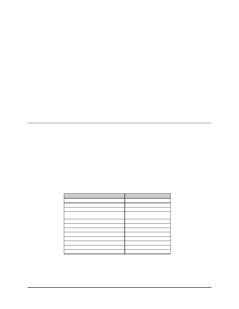
The modem consists of the following assemblies:
Assembly
Drawing #
Chassis with Power Supply
AS/5281-X
PCB, Demod/M&C
AS/4973
PCB, Interface Daughter (RS-422)
AS/2524
(See note below)
PCB, Interface Daughter (V.35)
AS/2532 or AS/4326
(See note below)
PCB, Interface Daughter (RS232)
AS/2533
(See note below)
PCB, Interface Daughter (ASYNC)
AS/4089
(See note below)
PCB, Interface Daughter (ADPCM)
AS/3916
(See note below)
PCB, Modulator
AS/2522
ASIC, Sequential Decoder
IC/EFD 8858 (optional)
PCB, Mod RF
AS/3995-X
PCB, Demod RF
AS/4401-X
PCB, Reed-Solomon (SDM-100)
AS/3708-2
Where X = various options available on the modulator and demodulator boards.
Refer to Table 5-2 for more information on the options available for each board.
Note: Only one interface option is shipped per modem.