1 purpose and function – Comtech EF Data SDM-100A User Manual
Page 18
Introduction
SDM-100A Satellite Modem
1–2
Rev.
0
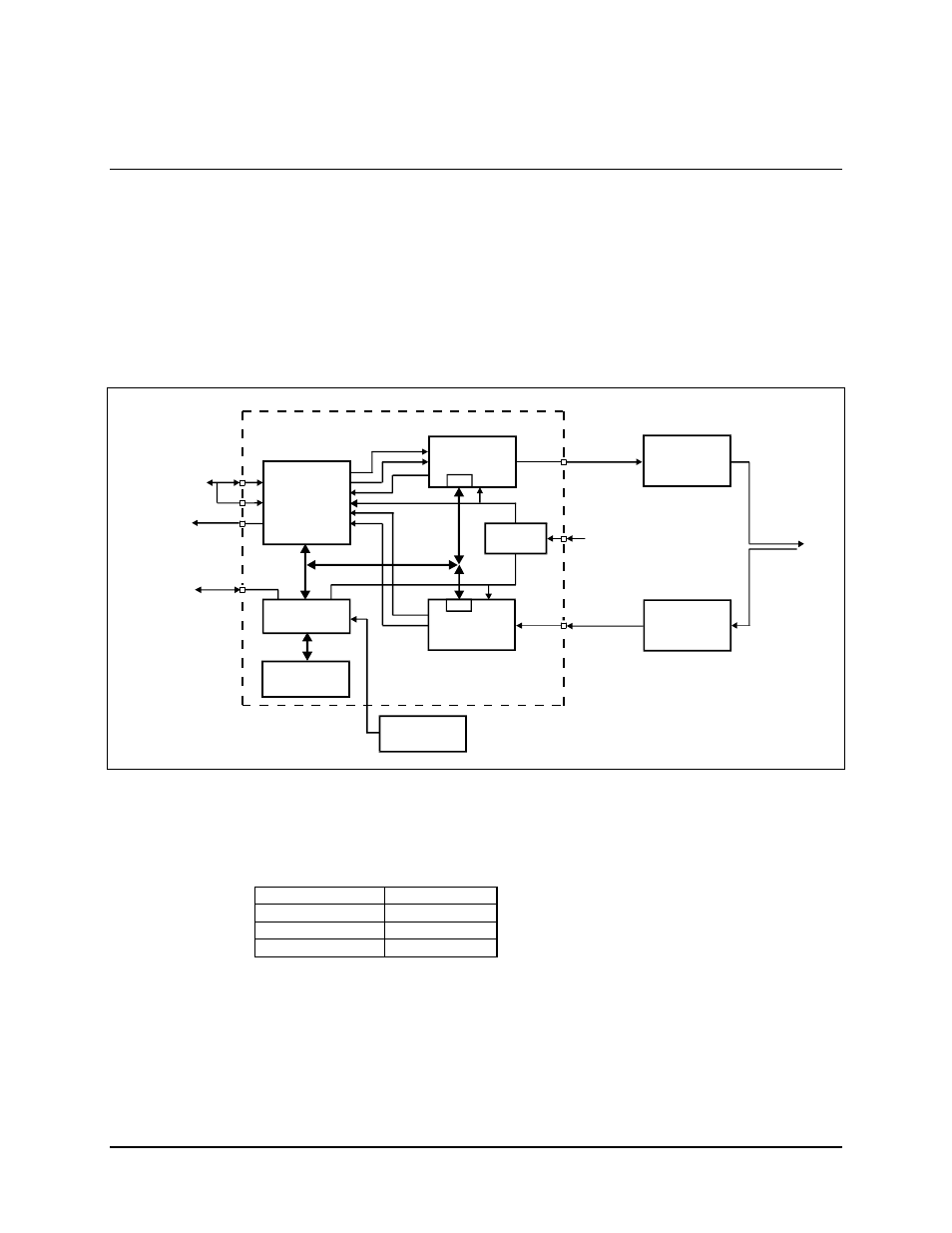
1.1 Purpose and Function
The modem is ideally suited for networks implemented with digitized voice compressors.
These types of circuits require the minimum processing delay provided by the modem’s
Viterbi decoder. A system block diagram is shown in Figure 1-2.
The modem is also employed in transportable applications, where small size and low
power consumption are important.
SDM-100A
SATELLITE MODEM
J8
ADPCM
RS-232,
RS-422,
V.35, or
ASYNC
DATA
CLK
SCT
ENCODER/
MODULATOR
M&C
M&C
CP1
IF OUTPUT
TRANSMIT RF
EQUIPMENT
50 to 180 MHz
-5 to -30 dBm
INTERFACE
EXT.
CLOCK
CUSTOMER
DATA I/O
J7
J8
ALARMS
FORM C
CONTACTS
COMMAND
BUS
POW ER
SUPPLY
90 to 264 VAC,
47 to 63 Hz
ANTENNA
REMOTE
SERIAL
INTERFACE
J6
MONITOR &
CONTROL
DATA
CLK
DECODER
DEMOD
CP2
IF INPUT
50 to 90 MHz
100 to 180 MHz
-30 to -55 dBm
RECEIVE RF
EQUIPMENT
DISPLAY &
KEYPAD
FRONT PANEL
REMOTE (OPT.)
Figure 1-2. SDM-100A Block Diagram
The modem provides total flexibility in selection of the following data rates:
19.2 to 128 kbit/s
1/2 rate
28.8 to 192 kbit/s
3/4 rate
33.6 to 224 kbit/s
7/8 rate QPSK
9.6 to 64 kbit/s
1/2 rate BPSK
These parameters, as well as selection of elastic buffer, scrambler, differential encoder,
power levels, and carrier frequencies, can be selected from the front panel, or by remote
control via a serial interface.
Since the modem is software defined, it can be programmed to be end-to-end compatible
with other manufacturer’s modems at similar rates.