Figure 4-2. bpsk ordering, viterbi – Comtech EF Data SDM-100A User Manual
Page 120
Theory of Operation
SDM-100A Satellite Modem
4–4
Rev.
0
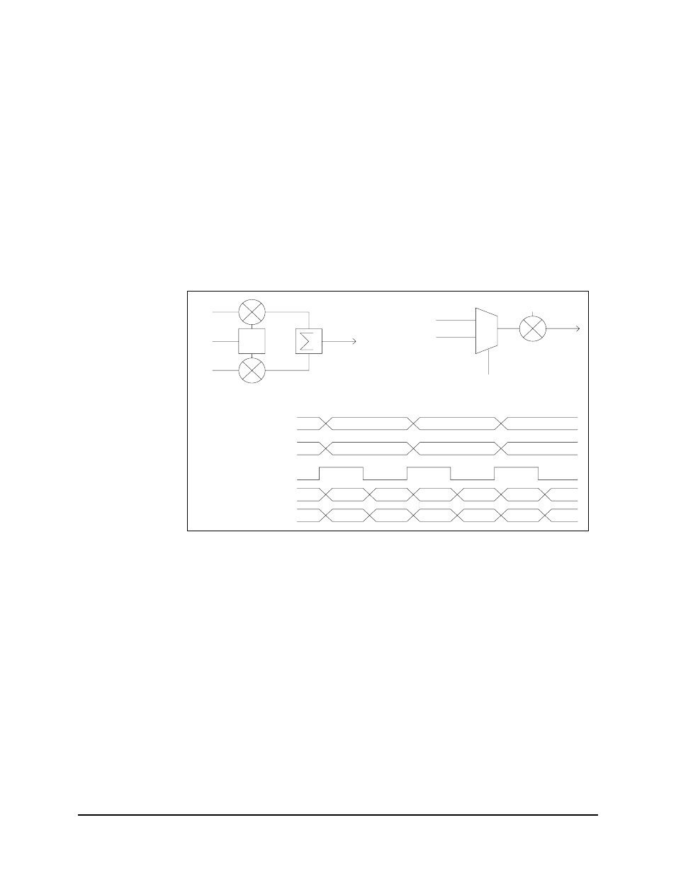
In the normal (or “Standard”) operation, the I channel data is output from the MUX first,
followed by Q channel data. If this order of data does not match the receive BPSK
ordering, the modem will not lock. The TX and RX BPSK ordering must be the same in
order to get the receiver to lock. Selecting “Non-Standard,” or inverted phase, for TX
BPSK ordering will force the MUX to output the In-phase and Quadrature (I&Q) data
streams in the opposite order, thereby matching the RX BPSK ordering being received
from the other end.
Refer to Figure 4-2 for a timing diagram and schematic diagram explaining BPSK
ordering.
I
QPSK
Q
Q
I
Q
I
Q
I
SEL
MUX
OUT
BPSK
STANDARD
NON-STANDARD
BPSK
MUX
OUT
Q
I
Q
I
Q
I
I
LO
0
TX IF
-90
Q
I
1
LO
TX IF
0
Q
SELECT
Figure 4-2. BPSK Ordering, Viterbi