1 data i/o interface (j8), 2 remote (j6) – Comtech EF Data SDM-100A User Manual
Page 32
Installation
SDM-100A Satellite Modem
2–6
Rev.
0
2.4.1 DATA I/O Interface (J8)
The DATA I/O interface connector is used to interface data input and output signals to
and from the modem. The DATA I/O connects to the customer terrestrial equipment
directly or through a protection switch.
The DATA I/O interface can be MIL-STD-188, RS-422/449, V.35, or RS-232-C.
The interface module of the modem is mounted directly on the modulator board. The
modem operates with a single interface configuration. Field changes are easily done by
changing the interface module (refer to Chapter 4).
2.4.2 Remote (J6)
The Remote connector on the modem is used to interface the Monitor and Control
(M&C) functions to a remote location. This interface can be either RS-232-C or RS-485.
For a more information on the remote interface, refer to Chapter 4.
The remote interface is provided on a 9-pin female D connector. Screw locks are
provided for mechanical security of the mating connector.
The remote connector is a Data Circuit Terminating Equipment (DCE) interface.
There are jumpers on the demodulator board that must be set to select either RS-485 or
RS-232-C remote interface.
Refer to Chapter 4 for configuration information.
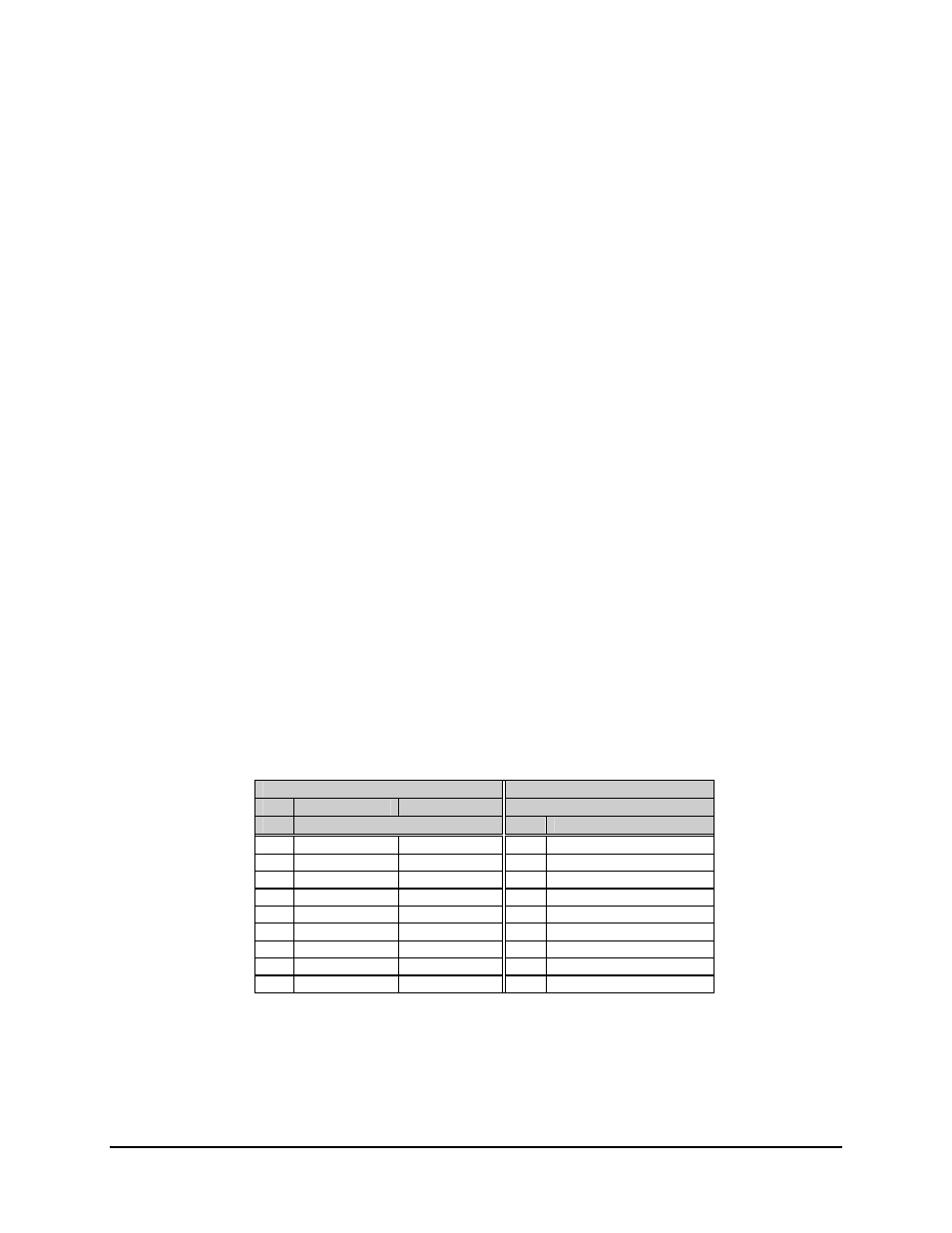
RS-485
RS-232-C
4-Wire Mode
2-Wire Mode
4- and 2-Wire Mode
Pin
Name
Pin
Name
1 GND
GND
1
2
2 RD
(RX)
3
3 TD
(TX)
4
+ TX
+ RX/TX
4
5
- TX
- RX/TX
5
GND
6
6
Data Signal Rate (DSR)
7
7
Request to Send (RTS)
8
+RX
+ RX/TX
8
Clear to Send (CTS)
9
- RX
- RX/TX
9