Yaskawa MP900 Teach Pendant User Manual
Page 37
Operation
3.1.3 Operation Settings
3 -6
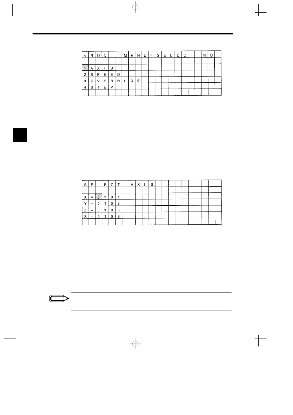
Figure 3.6
RUN Menu Screen
J
Selecting the Axis
This section describes how to set the controlled axes using the Teach Pendant’s operation keys
(logical axes). Up to a maximum of 4 logical axes can be controlled at the same time from the
Teach Pendant.
There are two methods for setting this information, as shown in the following procedures.
Setting a Physical Address for a Logical Axis
1. Select the logical axis name to be set using the Up and Down Cursor Keys.
The cursor will flash in the space to the right of the logical axis name.
Figure 3.7
Logical Axis Setting Screen
2. Input the physical axis address using the Numeric Keys and press the ENT Key to confirm.
The physical axis address will be set in the space to the right of the logical axis name. If
the physical axis address set in the above procedure is already set for another address, the
most recent setting will be effective. (The existing setting will be deleted and the display
will be cleared.)
3. To delete existing settings, press the DEL Key to delete all the physical axis addresses and
then press the ENT Key.
The physical axis address to the right of the logical axis name will be cleared.
Notation for the Physical Address
If the line number is 1 and the station number is 3, the physical address is expressed as 0103.
3
INFO