7 setting parameters – Yaskawa MP900 Teach Pendant User Manual
Page 52
3.1 Settings and Displays
3 -21
2. Move the cursor to the row to be displayed using the Up and Down Cursor Keys.
3. Input the register and bit numbers using the Numeric Keys and press the Enter Key to
confirm.
IB will be displayed automatically when the Numeric Keys are used.
4. ENA (Enable) or DIS (Disable) will be displayed.
5. To delete the displayed data, move the cursor to the data and press the DEL Key while
pressing the SHIFT Key.
6. To switch between ENA and DIS, move the cursor to ENA/DIS and press the Left or Right
Cursor Keys while pressing the SHIFT Key.
The ON/OFF status can be controlled when DIS is displayed. Move the cursor to ON/OFF
and press the Left or Right Cursor Key while pressing the SHIFT Key.
7. As in step 6., move the cursor to the # register display and overwrite the bit address or #
register using the Numeric and ENT Keys.
Hexadecimal digits A to F can be input by pressing the Numeric Keys 0 to 5 while pressing
the SHIFT Key.
1.
The
Left and Right Cursor Keys are enabled for the currently displayed row.
2. A maximum of 5 items of data can be displayed on one screen. (A maximum of 20 items of data can be set
and the screen can be scrolled between them.)
3. When switching to other screens, the currently displayed registers will be recorded, so when you return to
the original screen the same registers will be displayed.
4. It is possible to disable a setting only when the coil is being used in a ladder logic program.
J
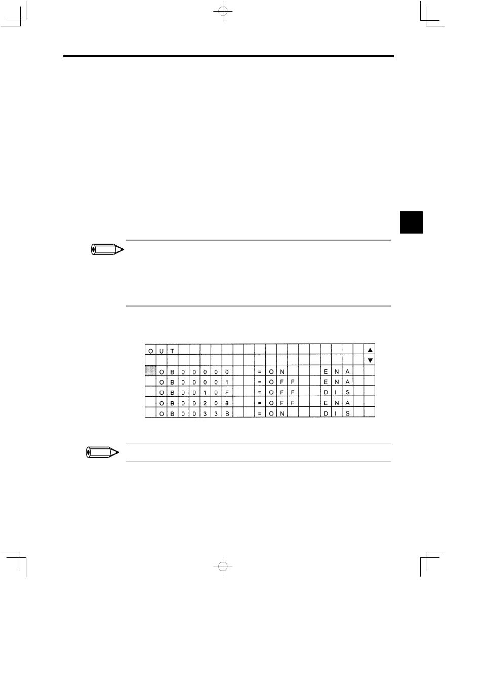
Setting Output Coils (OUT)
The procedure for setting output coils is the same as for input relays.
Figure 3.41 Output Coil Screen
When a register with no I/O definition is specified, the register will be displayed, but it cannot be set.
3.1.7 Setting Parameters
J
Parameter Menu Screen
The Parameter Menu Screen is shown in the following diagram.
3
INFO
INFO