Yaskawa MP900 Teach Pendant User Manual
Page 60
3.1 Settings and Displays
3 -29
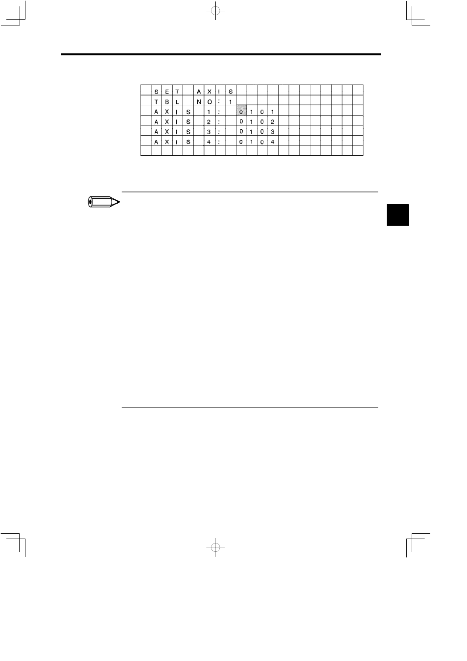
Figure 3.55 Point Table Physical Axis Number Setting Screen
1.
For each table, data for the 16 axes is saved.
Example of register allocations:
The register a llocations when the t able number i s 1, t he first register i s ML00100, the number of points i s
100, and the axis number is 4 as shown below.
X
Y
Z
S
P0001
ML00100
ML00300 ML00500 ML00700
P0002
ML00102
ML00302 ML00502 ML00702
P0003
ML00104
ML00304 ML00504 ML00704
S
S
S
S
S
S
S
S
S
S
P0100
ML00298
ML00498 ML00698 ML00898
2. M registers are used for the table numbers 1 to 4, and C registers for numbers 5 to 8.
3. When the table to be saved is the same as an existing table or system working area, or the table is not within
range, the input values cannot be saved. The examples are shown below.
•
When 100 or lower of the M registers is set for START (the area used by the Controller)
•
When STOP exceeds the maximum value of M registers (M registers: 32768 or more, C registers:
4096 or more)
4. When M registers or C registers are used other than for the Teach Pendant, confirm that the register range
is not the same as the table area to be saved.
5. “EDIT” is displayed on the screen during inputting setting data. At this time, the cursor cannot be moved
to other axis using the Up and Down Cursor Keys.
Resetting Point Tables
To reset a table, save the table filled with zeros (0).
J
Editing Point Tables
Point table can be edited using the procedure outlined in 3.1.7 Setting Parameters. Switching
between screens is possible using the same method as switching between parameters. Data can
be input only in decimal form.
3
INFO