Yaskawa MP900 Teach Pendant User Manual
Page 53
Operation
3.1.7 Setting Parameters
3 -22
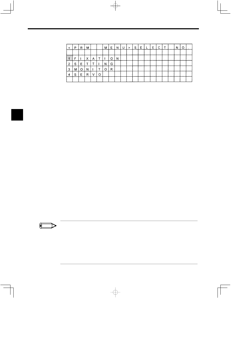
Figure 3.42 Parameter Menu Screen
The procedure for switching screens is described below.
Switching Parameters
D
The screen can be scrolled or another parameter selected using the Up and Down Cursor
Keys.
D
The screen can be scrolled one page at a time using the NEXT/PREV Keys.
Switching Axes
The next axis can be selected using the Left or Right Cursor Keys. (In order of the logical
axis or physical axis address.)
Other Switching Operations
Toswitchbetweenthe logicalaxisdisplay andthe physicalaxisdisplay,pressthe
LeftorRightCursorKeys
while pressing the
DISP CHG Key.
Editing Parameters
The procedure for editing parameters is described below.
1. Move the cursor to the parameter number using the Up and Down Cursor Keys and press
the ENT Key. The cursor will move to the setting area.
2. Input the numeric value using the Numeric Keys.
3. Press the ENT Key to confirm. The cursor will move to the parameter number area.
Note:
Write-prohibited parameters will not be moved to the setting area when the ENT key
is pressed.
1.
Some parameters (memory switches, modes, flag settings, etc.) are displayed in hexadecimal (displayed as
jjjj
H) for parameter display/setting. Monitoring parameters cannot be changed.
2. Servo parameters cannot be changed under the following circumstances.
S
When b0 of setup parameter No. 2: Servo drive RUN setting OWjj01 is ON.
S
When the Servo of the Servopack whose parameters you are attempting to change is ON.
S
When an alarm has occurred in the Se rvopack whose parameters you are a ttempting to c hange. (Except
when ILjj22 is zero.)
3. SVA Servo parameters cannot be monitored.
3
INFO