Yaskawa MP900 Teach Pendant User Manual
Page 39
Operation
3.1.3 Operation Settings
3 -8
1.
When more than one Module is connected to the MP920 or CP-9200SH, axes can be set for 1 to 16 Modules.
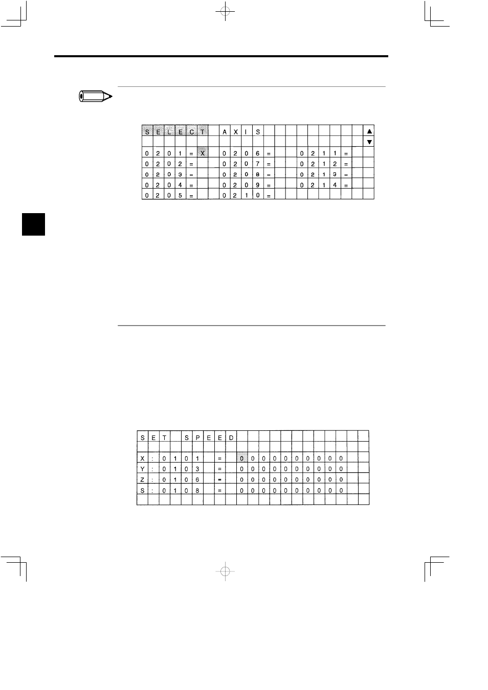
At this time, “ Y ” and “ B ” will be displayed on the upper-right of the screen. (Refer to the following Screen.)
To switch among the Modules, press the NEXT or PREV Keys from the Physical Axis Setting Screen.
Figure 3.9
Physical Axis Setting Screen
S B
: When this symbol is displayed, use the NEXT Key to increase one number at a time.
S Y
: When this symbol is displayed, use the PREV Key to decrease one number at a time.
2. When the Axis Selecting Function is selected, the Logical Axis Setting Screen will be displayed first.
To switch between the Logical Axis Setting Screen and t he Physical Axis Setting Screen, press the Left and
Right Cursor Keys while pressing the DISP CHG Key. (The contents of the L ogical Axis Setting Screen
and the Physical Axis Setting Screen are always the same.)
3. The procedure for switching between the Logical Axis Setting Screen and the Physical Axis Setting Screen
is the same from other setting screens.
4. When a logical axis has not been set on the Physical Axis Setting Screen, the physical axis address will be
displayed as 0101 when the screen is switched to the Logical Axis Setting Screen.
J
Speed Settings
This section describes how to set the rapid transverse speed for jogging and stepping opera-
tions. There are two methods for setting this information, as shown in the following proce-
dures.
Using the Logical Axis
1. Move the cursor to the input area of the logical axis name to be set, using the Up and Down
Cursor Keys.
Figure 3.10 Set Speed Screen 1
3
INFO