Servopacks, 5t rial operation (checking servomotor operation) – Yaskawa Sigma-5 User Manual: Setup for Rotary Motors User Manual
Page 100
5.2 Inspection and Checking before Trial Operation
5-3
5
T
rial Operation (Checking Servomotor Operation)
SERVOPACKs
Inspect and check the following items, and take appropriate measures before per-
forming trial operation if any problem exists.
• Are all installation, wiring and connections correct?
• Is the correct power supply voltage being supplied to the SERVOPACK?
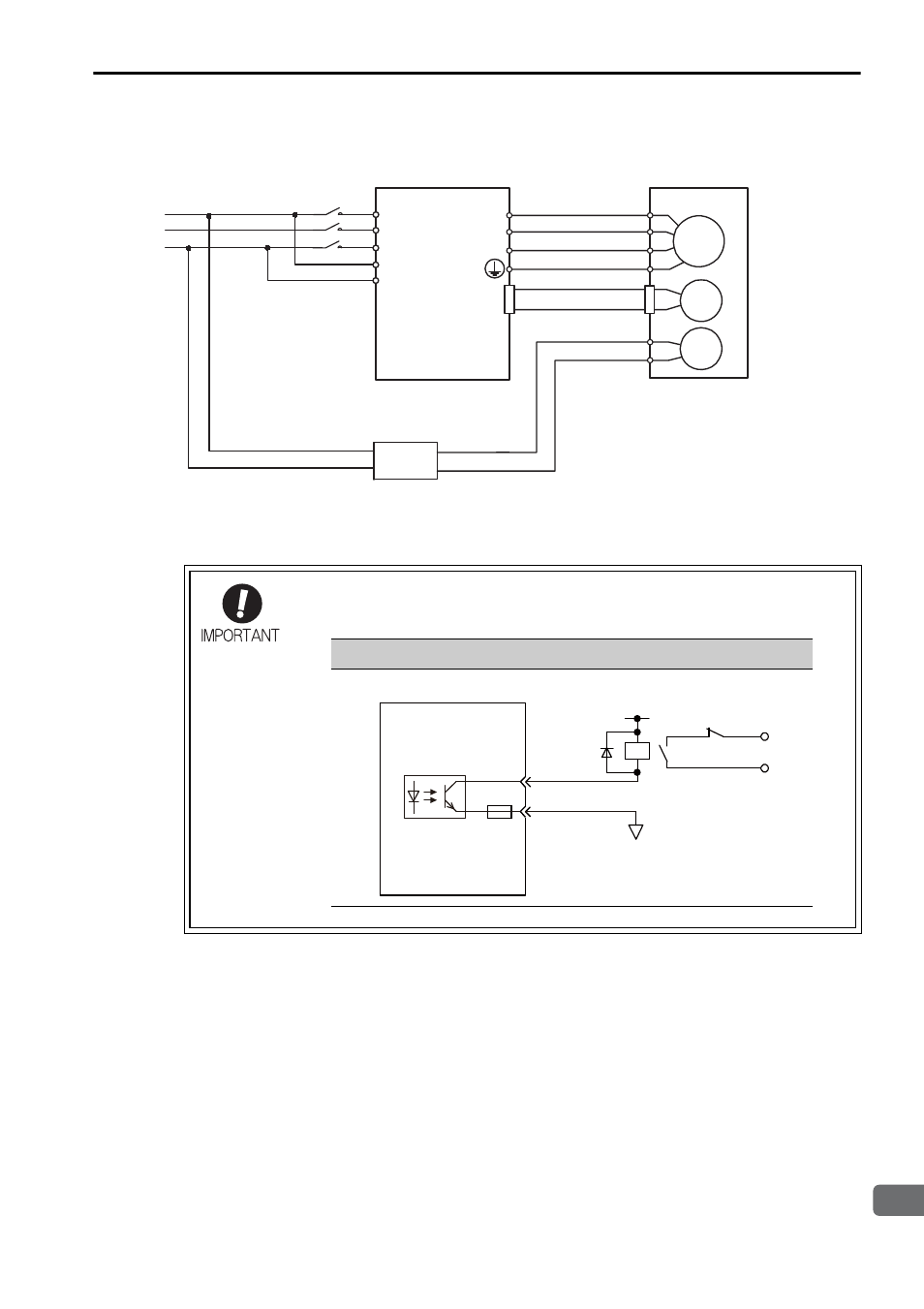
Configure the relay circuit to apply the holding brake by the emer-
gency stop.
Servomotor
with brake
SERVOPACK
Power supply
A 24 VDC power supply is not included.
Brake power supply Input voltage of 200 V: LPSE-2H01-E
M
BK
ENC
U
V
W
CN2
AC
DC
L1
L2
L3
L1C
L2C
24 VDC power supply
or
Brake power supply
24 VDC or 90 VDC
Input voltage of 100 V: LPDE-1H01-E
An example of the circuit wiring
Relay Circuit Example
0 V
Emergency stop
5 to 24 VDC
SERVOPACK
Photocoupler