3 main circuit wiring, 1 names and functions of main circuit terminals – Yaskawa Sigma-5 User Manual: Setup for Rotary Motors User Manual
Page 77
Advertising
3.3 Main Circuit Wiring
3-19
3
Wiring and Connection
3.3
Main Circuit Wiring
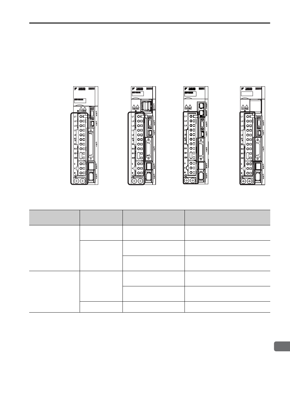
The names, specifications, and functions of the main circuit terminals required for
trial operation are given below.
3.3.1 Names and Functions of Main Circuit Terminals
Analog Pulse Models
M-II Models
M-III Models
Command Option
Attachable Types
SGDV-1R6AE1A
Name
Terminal
Symbols
Model SGDV-
Description
Main circuit input
terminals
L1, L2
F
Single-phase 100 to 115 V,
+10% to -15% (50/60 Hz)
L1, L2, L3
A
Three-phase 200 to 230 V,
+10% to -15% (50/60 Hz)
D
Three-phase 380 to 480 V,
+10% to -15% (50/60 Hz)
Control power
input terminals
L1C, L2C
F
Single-phase 100 to 115 V,
+10% to -15% (50/60 Hz)
A
Single-phase 200 to 230 V,
+10% to -15% (50/60 Hz)
24V, 0V
D
24 VDC,
±
15%
Advertising