2 system configuration diagram 3-9 – Yaskawa Sigma-5 User Manual: Setup for Rotary Motors User Manual
Page 67
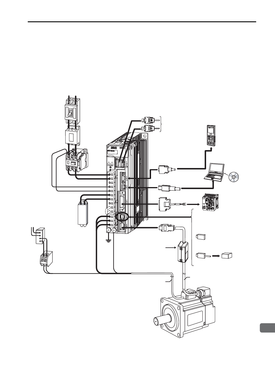
3.2 System Configuration Diagram
3-9
3
Wiring and Connection
• Using a Single-phase, 200-V Power Supply
The
Σ-V Series SERVOPACK for a 200-V power supply input has input specifica-
tions for a three-phase power supply, but some models can also be used with a single-
phase 200-V power supply. For details, refer to
Σ
-V Series User's Manual Design and
Maintenance Rotational Motor/MECHATROLINK-II Communications Reference
(SIEP S800000 46).
∗1. Use a 24 VDC power supply. (not included.)
∗2. Before connecting an external regenerative resistor to the SERVOPACK, refer to 3.4 Con-
necting Regenerative Resistors.
200 VAC
Connect to the
MECHATROLINK-II
SGDV-
A11
SERVOPACK
SGMJV/SGMAV/SGMPS/
SGMGV/SGMSV
Servomotor
Power supply
Single-phase 200 VAC
Noise filter
Molded-case
circuit breaker
(MCCB)
Protects the power supply
line by shutting the
circuit OFF when
overcurrent is
detected.
Used to eliminate
external noise from
the power line.
Magnetic
contactor
Turns the servo
ON and OFF.
Install a surge
absorber.
Brake power supply*
1
Magnetic contactor
Regenerative
resistor*
2
Used for a servomotor
with a brake.
Turns the brake power supply
ON and OFF.
Install a surge absorber.
Motor main
circuit cable
Encoder cable
When not using the safety
function, use the SERVOPACK
with the safety function jumper
connector (JZSP-CVH05-E,
provided as an accessory)
inserted.
When using the safety function,
insert a connection cable
specifically for the safety function.
Safety function
devices
I/O signal cable
Connection cable
for digital operator
Connection cable
for personal computer
Digital
operator
Personal
computer
Host controller
Battery case
(when an absolute
encoder is used.)
R
T