2 installation standards – Yaskawa Sigma-5 User Manual: Setup for Rotary Motors User Manual
Page 32
2.3 SERVOPACK Installation
2-11
2
Installation
2.3.2 Installation Standards
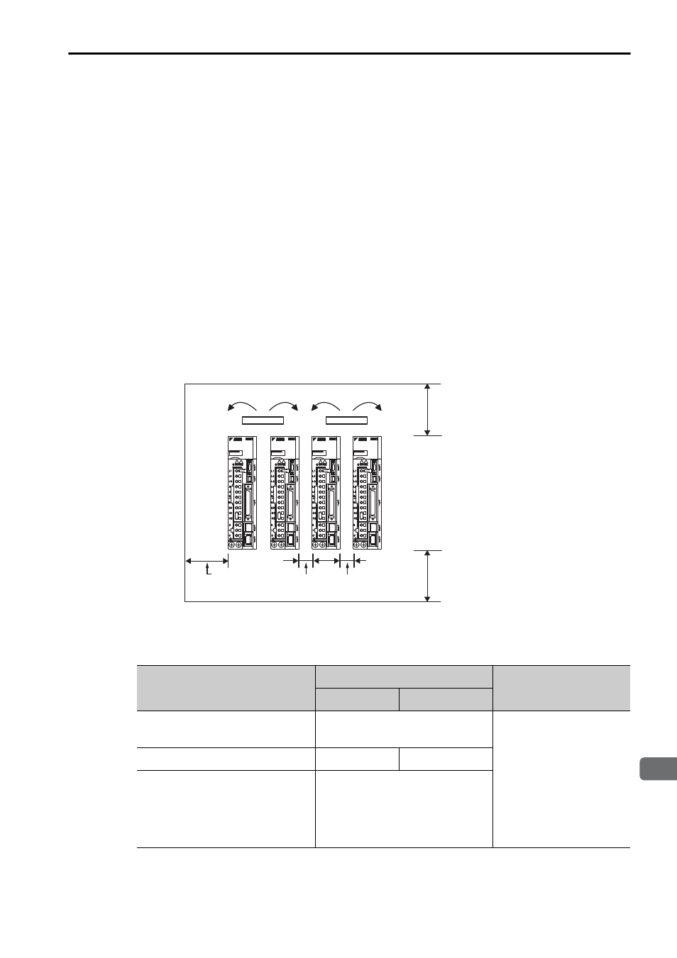
Observe the standards for mounting SERVOPACKs in control panels, including those
for the mounting SERVOPACKs side by side in one control panel as shown in the
following illustration.
Note: For SERVOPACKs of command option attachable type, installation conditions may dif-
fer depending on the attached option module. For details, refer to the user’s manual for
each option module.
• SERVOPACK Mounting Orientation
Mount the SERVOPACK vertically to the wall, with the front panel (the side with the
panel operator display) facing out.
• Cooling
Refer to the following diagram and leave sufficient space for cooling by fans and nat-
ural convection.
• Mounting SERVOPACKs Side by Side in a Control Panel
Leave sufficient space on each side and at the top and the bottom of each SERVO-
PACK. The width on each side varies in accordance with the models of the SERVO-
PACKS used.
Also install cooling fans above the SERVOPACKs to disperse local pockets of
warmer air around the SERVOPACKs.
Fan
30 mm
or more
40 mm or more
40 mm or more
Width varies with
SERVOPACK model
Fan
SERVOPACK Model
SGDV-
Side
Top and bottom
Left
Right
R70F, R90F, 2R1F,
R70A, R90A, 1R6A, 2R8A
1 mm or more
40 mm or more
2R8F, 3R8A, 5R5A, 7R6A
1 mm or more 10 mm or more
120A, 180A, 200A, 330A,
470A, 550A, 590A, 780A,
1R9D, 3R5D, 5R4D, 8R4D,
120D, 170D, 210D, 260D,
280D, 370D
10 mm or more