4 emc installation conditions, 1 sgdv-****01* (analog pulse model), 1 sgdv-01 (analog pulse model) – Yaskawa Sigma-5 User Manual: Setup for Rotary Motors User Manual
Page 34: Single-phase 100 v, 2installation
2.4 EMC Installation Conditions
2-13
2
Installation
2.4
EMC Installation Conditions
This section describes the recommended installation conditions that satisfy EMC
guidelines for each model of the SGDV SERVOPACK. The conditions required for
the standard type (base-mounted) of SERVOPACK are described. Refer to this sec-
tion for other SERVOPACK models such as the rack-mounted types as well.
This section describes the EMC installation conditions satisfied in test conditions
prepared by Yaskawa. The actual EMC level may differ depending on the actual sys-
tem’s configuration, wiring, and other conditions. However, because this product is
built-in, check that the following conditions are still met after being installed in the
user’s product.
The applicable standards are EN55011 group 1 class A, EN61800-3, and EN61000-6-
2.
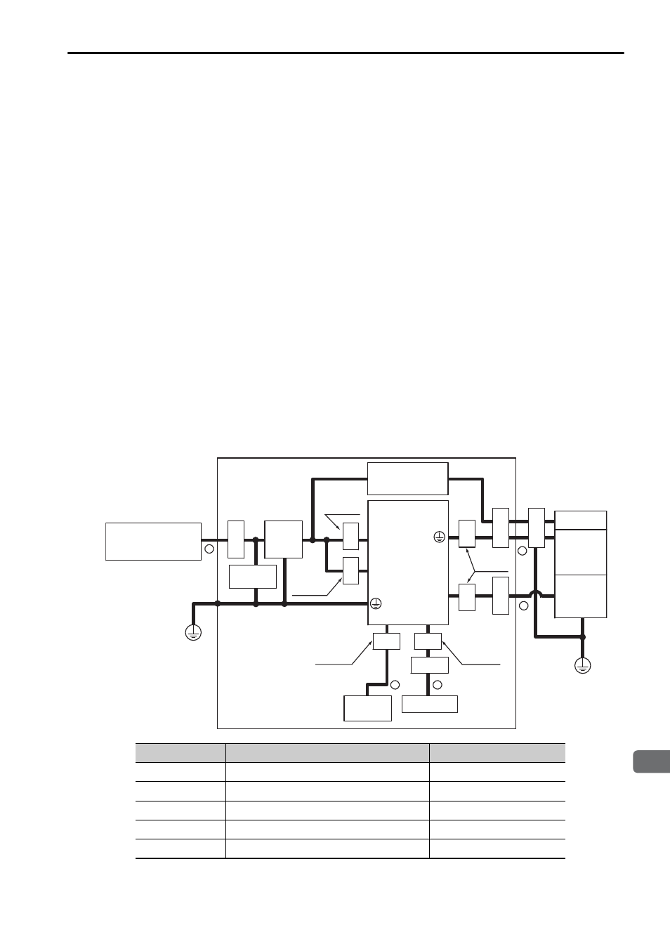
2.4.1 SGDV-01 (Analog Pulse Model)
Single-phase 100 V
• SGDV-F01A ( = R70, R90, 2R1, 2R8)
Symbol
Cable Name
Specification
c
I/O signal cable
Shield cable
d
Safety signal cable
Shield cable
e
Motor main circuit cable
Shield cable
f
Encoder cable
Shield cable
g
Main circuit cable
Shield cable
Power supply:
Single-phase
100 VAC
U, V, W
L1, L2
L1C, L2C
CN2
CN1
Shield box
SERVOPACK
PE
PE
Encoder
Servomotor
Brake
1
3
4
5
Clamp
Noise
filter
Brake Power
Supply
Clamp
Clamp
Clamp
CN8
2
Surge
absorber
Two turn
One turn
Core
Core
Core
Core
Core
Core
Two turn
Two turn
Clamp
Host
controller
Safety unit
One turn