Input channel − aux sends, Auxiliary channels flow diagram, Nnput channel − wux sends – QSC Audio TouchMix-30 Pro 32-Channel Compact Digital Mixer with Touchscreen User Manual
Page 57: Wuxiliary channels flow diagram, Input channels
48
1001108-01-F
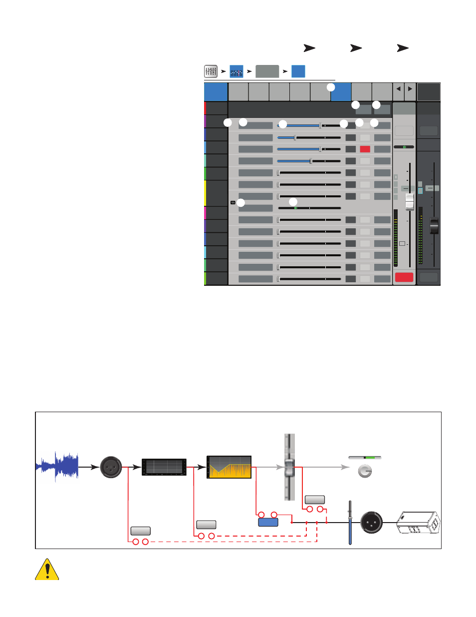
Input Channel − Aux Sends
Auxiliary outputs are used to create a mix for stage
monitors, in ear monitors, remote speakers or
video / broadcast. The auxes may be linked for stereo.
1.
Auxes tab
– Selects the Aux Sends screen
2.
Aux Overview button
– Navigates to
the Aux Overview which displays all Aux mixes on a
single screen.
3.
Reset button
– Resets all Aux Sends
controls, for the selected input channel, to the
factory default.
4.
Aux mix system number
– Displays the
number of the associated Aux Output.
5.
Aux mix friendly name / button
–
Displays the user-defined Aux mix name. Touch to
navigate to the associated Aux output controls.
6.
Aux send sliders
– Sets the level of audio
sent from the channel to the Aux mix; -40 dB (-Inf)
is off.
7. Level – Provides a numeric display of the Aux
send level.
8.
Mute
– Mutes the send from the channel to the
associated Aux mix. Does not effect any other mixes
or sends.
9. Pick-off point button – Indicates if the Aux Buss is
taking a
Pre Fdr/ Post Fdr / Pre Dyn
/ Pre All signal
. Touch to navigate to the associated Aux output controls to change the setting. Affects all sends for the associated
aux mix.
10.
Aux link indicator
– Indicates the Aux channels are linked. You can link Aux channels from the Input channel Aux Sends screen
by touching one of the Aux mix buttons, or one of the pick-off buttons. Both take you to the Aux channel Setup screen where linking is
accomplished.
11.
Aux Sends pan slider
– Pans the signal between a linked pair of auxes.
Auxiliary Channels Flow Diagram
The Pre All, Pre Dyn, Pre Fader, and Post Fader buttons are radio-buttons that provide options for where the Aux Outputs get their signal. In the
figure below, the Pre Fader button is selected.
OIUT!:
For detailed information, refer to the Block Diagram.
Home
Touch an
Input Bank
Touch a
Channel
Touch
Auxes
Tab
∞
Inputs 1-8
Cue
L
C
R
Mic
1
10
5
u
5
10
20
0
40
10
Main
L/R
10
5
u
5
10
20
0
40
10
Mute
Mute
Overview
Comp
Gate
Auxes
Presets
Setup
1
Aux 2
Joe’s Aux
Aux 3
Aux 4
Aux 5
Aux 6
EQ
-40
-20
-10
10
U
2
3
4
5
6
7
8
9
10
11
12
13
14
-40
-20
-10
10
U
-40
-20
-10
10
U
-40
-20
-10
10
U
-40
-20
-10
10
U
-40
-20
-10
10
U
-40
-20
-10
10
U
C
-40
-20
-10
10
U
-40
-20
-10
10
U
-40
-20
-10
10
U
-40
-20
-10
10
U
-40
-20
-10
10
U
-40
-20
-10
10
U
Aux 7
Aux 8
Aux 9
Aux 10
Aux 11
Aux 12
Aux 13
Aux 14
Mute
Mute
Mute
Mute
Mute
Mute
Mute
Mute
Mute
Mute
Mute
Mute
Mute
Prev
Next
LR
1
2
3
4
5
6
7
8
Default
In 1
Main
Cue
In 1
Auxes
Main Mix
L/R
Scene:
Overview
Reset
Aux Sends
Joe’s Ears
Aux 1
Aux 2
Aux 2
Aux 3
Aux 3
Aux 4
Aux 4
Aux 5
Aux 5
Aux 6
Aux 6
Aux 7
Aux 7/8
Aux 9
Aux 9
Aux 10
Aux 10
Aux 11
Aux 11
Aux 12
Aux 12
Aux 13
Aux 13
Aux 14
Aux 14
-3.0
-28.0
-inf
-inf
-inf
-inf
Pre Dyn
Pre All
Post Fdr
Pre Fdr
FX
-inf
-inf
-inf
-inf
-inf
-3.0
-12.0
Pre Fdr
Pre Fdr
Pre Fdr
Pre Fdr
Pre Fdr
Pre Fdr
Pre Fdr
Pre Fdr
Pre Fdr
L
G
48
L
F
Inputs 1-8
2
3
1
6
8
5
7
9
4
11
10
Input
Channels
L
C
R
EQ
Dynamics
Channel
Fader
Channel
Pan
Aux
Sends
Audio
Input
Aux Outputs
Pre Fader
Pre All
Pre Dyn
Post Fader
-40
-20
-10
-5
5
10
U