Network diagram, Configuration procedure – H3C Technologies H3C S10500 Series Switches User Manual
Page 105
90
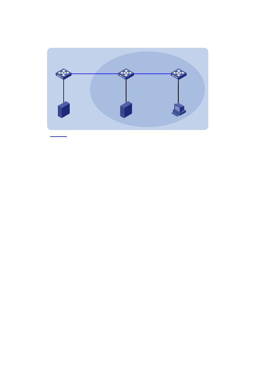
Network diagram
Figure 31 Network diagram for creating an RPF route
Switch A
Switch B
Switch C
Vlan-int102
30.1.1.2/24
Vlan-int101
20.1.1.2/24
Vlan-int101
20.1.1.1/24
Vlan-int102
30.1.1.1/24
Source 1
Source 2
Receiver
40.1.1.100/24
10.1.1.100/24
Multicast static route
Vlan-int200
40.1.1.1/24
Vlan-int100
10.1.1.1/24
OSPF domain
PIM-DM
50.1.1.100/24
Vlan-int300
50.1.1.1/24
Configuration procedure
1.
Configure IP addresses and unicast routing
Configure the IP address and subnet mask for each interface as per
. (details not shown)
Enable OSPF on Switch B and Switch C. Ensure the network-layer interoperation among Switch B and
Switch C. Ensure that the switches can dynamically update their routing information by leveraging the
unicast routing protocol. (details not shown)
2.
Enable IP multicast routing, and enable PIM-DM and IGMP
# Enable IP multicast routing on Switch C, enable PIM-DM on each interface, and enable IGMP on
VLAN-interface 100.
<SwitchC> system-view
[SwitchC] multicast routing-enable
[SwitchC] interface vlan-interface 100
[SwitchC-Vlan-interface100] igmp enable
[SwitchC-Vlan-interface100] pim dm
[SwitchC-Vlan-interface100] quit
[SwitchC] interface vlan-interface 101
[SwitchC-Vlan-interface101] pim dm
[SwitchC-Vlan-interface101] quit
# Enable IP multicast routing on Switch A and enable PIM-DM on each interface.
<SwitchA> system-view
[SwitchA] multicast routing-enable
[SwitchA] interface vlan-interface 300
[SwitchA-Vlan-interface300] pim dm
[SwitchA-Vlan-interface300] quit
[SwitchA] interface vlan-interface 102
[SwitchA-Vlan-interface102] pim dm
[SwitchA-Vlan-interface102] quit
The configuration on Switch B is similar to that on Switch A. (details not shown)