Configuration procedure – H3C Technologies H3C S10500 Series Switches User Manual
Page 242
227
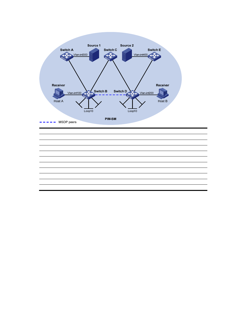
Figure 64 Network diagram for Anycast RP configuration
Loop0
Loop2
0
Lo
op20
Loop0
V
la
n
-i
n
t1
0
1
V
la
n
-i
n
t1
0
1
V
la
n
-in
t1
0
2
V
la
n
-in
t1
0
2
V
la
n
-in
t1
0
3
V
la
n
-in
t1
0
3
V
la
n
-i
n
t1
0
4
V
la
n
-i
n
t1
0
4
Device
Interface
IP address
Device
Interface
IP address
Source 1
—
10.110.5.100/24
Switch C
Vlan-int101
192.168.1.2/24
Source 2
—
10.110.6.100/24
Vlan-int102
192.168.2.2/24
Switch A
Vlan-int300
10.110.5.1/24
Switch D
Vlan-int200
10.110.3.1/24
Vlan-int103
10.110.2.2/24
Vlan-int104
10.110.4.1/24
Switch B
Vlan-int100
10.110.1.1/24
Vlan-int102
192.168.2.1/24
Vlan-int103
10.110.2.1/24
Loop0
2.2.2.2/32
Vlan-int101
192.168.1.1/24
Loop10
4.4.4.4/32
Loop0
1.1.1.1/32
Loop20
10.1.1.1/32
Loop10
3.3.3.3/32
Switch
E
Vlan-int400
10.110.6.1/24
Loop20
10.1.1.1/32
Vlan-int104
10.110.4.2/24
Configuration procedure
1.
Configure IP addresses and unicast routing
Configure the IP address and subnet mask for each interface as per
. (details not shown)
Configure OSPF for interconnection between the switches. Ensure the network-layer interoperation
among the switches, and ensure the dynamic update of routing information between the switches through
a unicast routing protocol. (details not shown)
2.
Enable IP multicast routing, and enable PIM-SM and IGMP
# Enable IP multicast routing on Switch B, enable PIM-SM on each interface, and enable IGMP on the
host-side interface VLAN-interface 100.
<SwitchB> system-view
[SwitchB] multicast routing-enable
[SwitchB] interface vlan-interface 100
[SwitchB-Vlan-interface100] igmp enable
[SwitchB-Vlan-interface100] pim sm
[SwitchB-Vlan-interface100] quit