Configuration procedure – H3C Technologies H3C S10500 Series Switches User Manual
Page 208
193
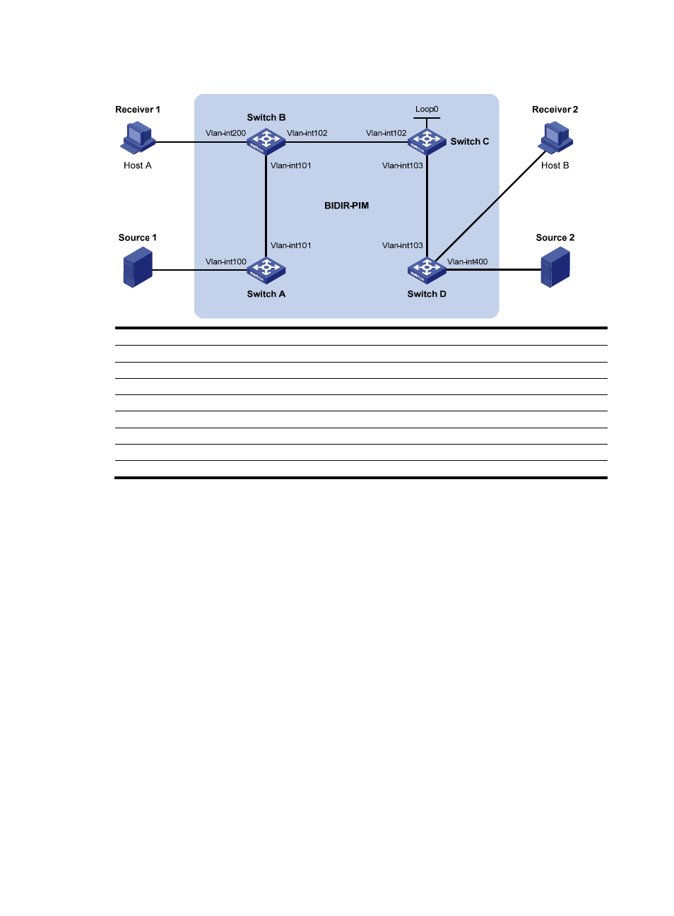
Figure 56 Network diagram for BIDIR-PIM configuration
Vlan-
in
t300
Device Interface IP
address
Device Interface IP
address
Switch A
Vlan-int100
192.168.1.1/24
Switch D
Vlan-int300
192.168.3.1/24
Vlan-int101 10.110.1.1/24
Vlan-int400 192.168.4.1/24
Switch
B Vlan-int200 192.168.2.1/24
Vlan-int103 10.110.3.2/24
Vlan-int101
10.110.1.2/24
Source
1
- 192.168.1.100/24
Vlan-int102
10.110.2.1/24
Source
2
- 192.168.4.100/24
Switch C
Vlan-int102
10.110.2.2/24
Receiver 1
-
192.168.2.100/24
Vlan-int103
10.110.3.1/24
Receiver
2
- 192.168.3.100/24
Loop0
1.1.1.1/32
Configuration procedure
1.
Configure IP addresses and unicast routing.
# Configure an IP address and subnet mask for each interface as per
. (Details not shown)
# Configure OSPF on the switches in the BIDIR-PIM domain to ensure network-layer reachability among
them. (Details not shown)
2.
Enable IP multicast routing, PIM-SM, BIDIR-PIM, and IGMP.
# On Switch A, enable IP multicast routing, enable PIM-SM on each interface, and enable BIDIR-PIM.
<SwitchA> system-view
[SwitchA] multicast routing-enable
[SwitchA] interface vlan-interface 100
[SwitchA-Vlan-interface100] pim sm
[SwitchA-Vlan-interface100] quit
[SwitchA] interface vlan-interface 101
[SwitchA-Vlan-interface101] pim sm
[SwitchA-Vlan-interface101] quit
[SwitchA] pim
[SwitchA-pim] bidir-pim enable
[SwitchA-pim] quit
# On Switch B, enable IP multicast routing, enable PIM-SM on each interface, enable IGMP on VLAN
interface 200, and enable BIDIR-PIM.