Configuration procedure – H3C Technologies H3C S10500 Series Switches User Manual
Page 54
39
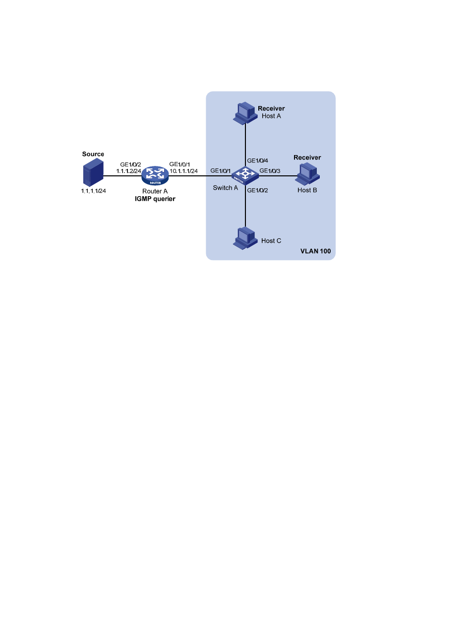
receiving multicast data, and that Switch A drops unknown multicast data and does not broadcast
the data to the VLAN where Switch A resides.
Figure 14 Network diagram for group policy simulated joining configuration
Configuration procedure
1.
Configure IP addresses
Configure an IP address and subnet mask for each interface as per
. (details not shown)
2.
Configure Router A
# Enable IP multicast routing, enable PIM-DM on each interface, and enable IGMP on GigabitEthernet
1/0/1.
<RouterA> system-view
[RouterA] multicast routing-enable
[RouterA] interface gigabitethernet 1/0/1
[RouterA-GigabitEthernet1/0/1] igmp enable
[RouterA-GigabitEthernet1/0/1] pim dm
[RouterA-GigabitEthernet1/0/1] quit
[RouterA] interface gigabitethernet 1/0/2
[RouterA-GigabitEthernet1/0/2] pim dm
[RouterA-GigabitEthernet1/0/2] quit
3.
Configure Switch A
# Enable IGMP snooping globally.
<SwitchA> system-view
[SwitchA] igmp-snooping
[SwitchA-igmp-snooping] quit
# Create VLAN 100, assign GigabitEthernet 1/0/1 through GigabitEthernet 1/0/4 to this VLAN, and
enable IGMP snooping and the function of dropping unknown multicast traffic in the VLAN.
[SwitchA] vlan 100
[SwitchA-vlan100] port gigabitethernet 1/0/1 to gigabitethernet 1/0/4
[SwitchA-vlan100] igmp-snooping enable
[SwitchA-vlan100] igmp-snooping drop-unknown