Configuration procedure – H3C Technologies H3C S10500 Series Switches User Manual
Page 426
411
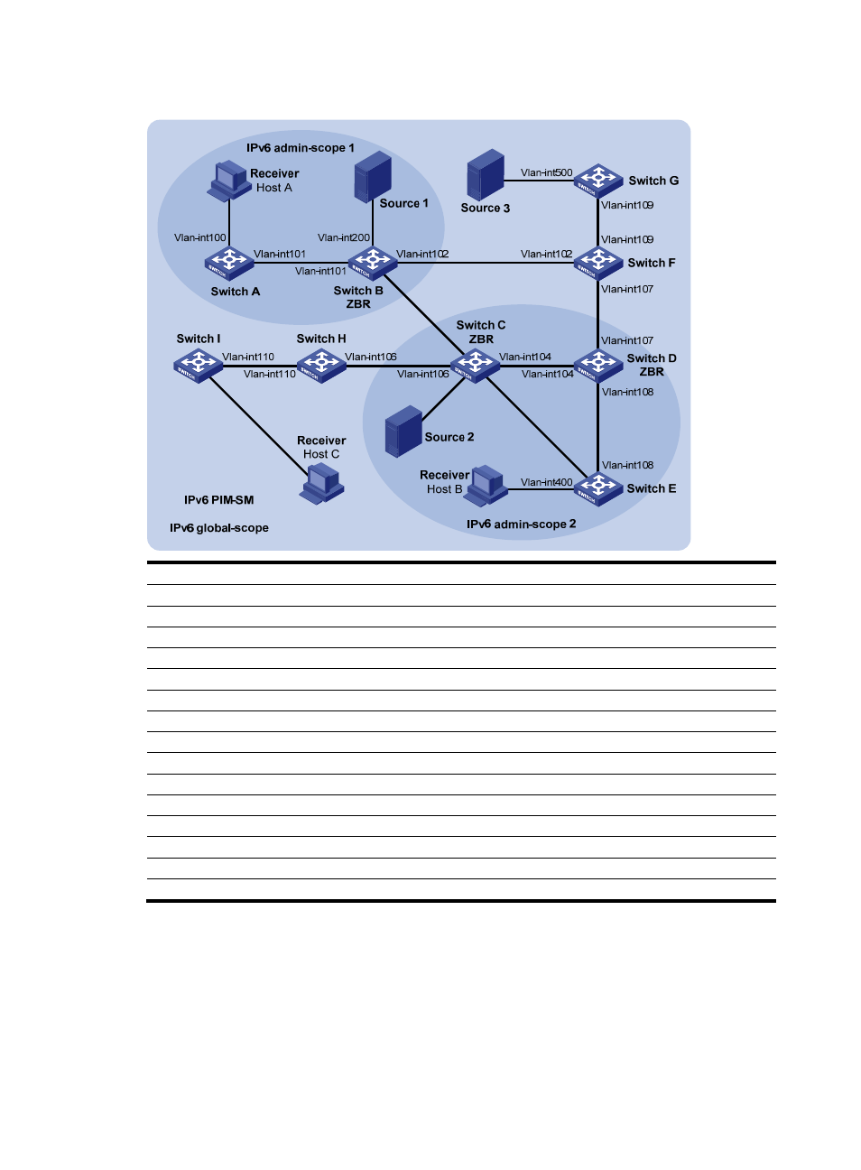
Figure 107 Network diagram for IPv6 PIM-SM admin-scope zone configuration
Vlan-
int1
05
Vl
an
-int103
Vl
an
-int300
Vlan-
in
t105
Vl
an-
int600
Vlan-
int1
03
Device Interface IPv6
address
Device Interface IPv6
address
Switch A
Vlan-int100
1001::1/64
Switch D
Vlan-int104
3002::2/64
Vlan-int101 1002::1/64
Vlan-int108 6001::1/64
Switch
B
Vlan-int200 2001::1/64
Vlan-int107 6002::1/64
Vlan-int101 1002::2/64 Switch
E
Vlan-int400 7001::1/64
Vlan-int103 2002::1/64
Vlan-int105 3003::2/64
Vlan-int102 2003::1/64
Vlan-int108 6001::2/64
Switch C
Vlan-int300
3001::1/64
Switch F
Vlan-int109
8001::1/64
Vlan-int104 3002::1/64
Vlan-int107 6002::2/64
Vlan-int105 3003::1/64
Vlan-int102 2003::2/64
Vlan-int103 2002::2/64 Switch
G Vlan-int500 9001::1/64
Vlan-int106 3004::1/64
Vlan-int109 8001::2/64
Switch H
Vlan-int110
4001::1/64
Source 1
—
2001::100/64
Vlan-int106
3004::2/64
Source
2
—
3001::100/64
Switch I
Vlan-int600
5001::1/64
Source 3
—
9001::100/64
Vlan-int110
4001::2/64
Configuration procedure
1.
Configure IPv6 addresses and unicast routing.
Configure the IPv6 address and prefix length for each interface as per
. (Details not shown)
Configure OSPFv3 on the switches in the IPv6 PIM-SM domain to ensure network-layer reachability
among them. (Details not shown)
2.
Enable IPv6 multicast routing and IPv6 administrative scoping, and enable IPv6 PIM-SM and MLD.