Configuration procedure – H3C Technologies H3C S10500 Series Switches User Manual
Page 196
181
•
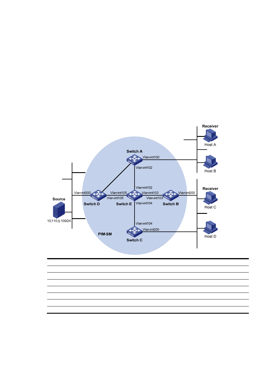
Host A and Host C are multicast receivers in two stub networks.
•
Switch D connects to the network that comprises the multicast source (Source) through
VLAN-interface 300.
•
Switch A connects to stub network N1 through VLAN-interface 100 and to Switch D and Switch E
through VLAN-interface 101 and VLAN-interface 102, respectively.
•
Switch B and Switch C connect to stub network N2 through their respective VLAN-interface 200,
and to Switch E through VLAN-interface 103 and VLAN-interface 104 respectively.
•
VLAN-interface 105 on Switch D and VLAN-interface 102 on Switch E act as C-BSRs and C-RPs. The
C-BSR on Switch E has a higher priority. The multicast group range served by the C-RP is
225.1.1.0/24. Modify the hash mask length to map a certain number of consecutive group
addresses within the range to the two C-RPs.
•
IGMPv2 will run between Switch A and N1 and between Switch B/Switch C and N2.
Figure 54 Network diagram for PIM-SM non- scoped zone configuration
Ether
net
Ether
net
E
thernet
N1
N2
Vlan-
in
t10
1
Vl
an
-int10
1
Device
Interface
IP address
Device
Interface
IP address
Switch A
Vlan-int100
10.110.1.1/24
Switch D
Vlan-int300
10.110.5.1/24
Vlan-int101
192.168.1.1/24
Vlan-int101
192.168.1.2/24
Vlan-int102
192.168.9.1/24
Vlan-int105
192.168.4.2/24
Switch B
Vlan-int200
10.110.2.1/24
Switch E
Vlan-int104
192.168.3.2/24
Vlan-int103
192.168.2.1/24
Vlan-int103
192.168.2.2/24
Switch C
Vlan-int200
10.110.2.2/24
Vlan-int102
192.168.9.2/24
Vlan-int104
192.168.3.1/24
Vlan-int105
192.168.4.1/24
Configuration procedure
1.
Configure IP addresses and unicast routing.
Configure the IP address and subnet mask for each interface as per
. (Details not shown)