Port-based multicast vlan, N in, Figure 22 – H3C Technologies H3C S10500 Series Switches User Manual
Page 79
64
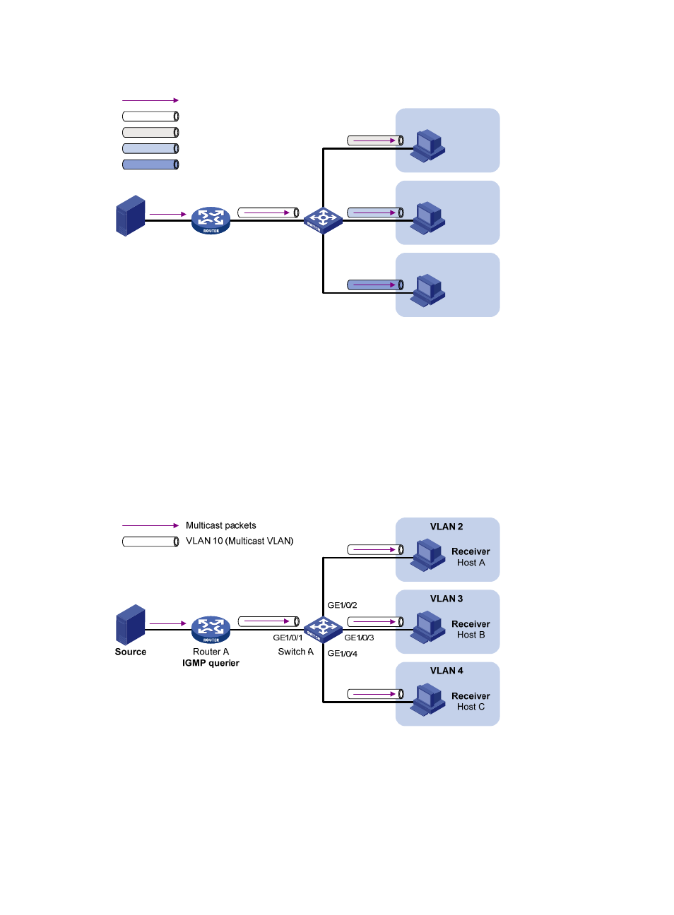
Figure 22 Sub-VLAN-based multicast VLAN
Source
Router A
IGMP querier
VLAN 2
VLAN 3
VLAN 4
Switch A
Receiver
Host A
Receiver
Host B
Receiver
Host C
Multicast packets
VLAN 2
VLAN 3
VLAN 4
VLAN 10 (Multicast VLAN)
After the configuration, IGMP snooping manages router ports in the multicast VLAN and member ports
in the sub-VLANs. When forwarding multicast data to Switch A, Router A sends only one copy of
multicast data to Switch A in the multicast VLAN, and Switch A distributes the data to the multicast
VLAN’s sub-VLANs that contain receivers.
Port-based multicast VLAN
As shown in
, Host A, Host B, and Host C are in different user VLANs. All the user ports (ports
with attached hosts) on Switch A are hybrid ports. On Switch A, configure VLAN 10 as a multicast VLAN,
assign all the user ports to VLAN 10, and enable IGMP snooping in the multicast VLAN and all the user
VLANs.
Figure 23 Port-based multicast VLAN
After the configuration, if Switch A receives an IGMP message on a user port, it tags the message with
the multicast VLAN ID and relays it to the IGMP querier, so that IGMP snooping can uniformly manage
the router port and member ports in the multicast VLAN. When Router A forwards multicast data to
Switch A, it sends only one copy of multicast data to Switch A in the multicast VLAN, and Switch A
distributes the data to all the member ports in the multicast VLAN.