4 analogue inputs, 6wiring, 7 control element – Pilz PMCprotego D.72/000/0/0/2/208-480VAC User Manual
Page 134
6.7
Control element
6
Wiring
Pilz GmbH & Co. KG, Felix-Wankel-Straße 2, 73760 Ostfildern, Germany
Telephone: +49 711 3409-0, Telefax: +49 711 3409-133, E-Mail: [email protected]
6-26
6.7.4
Analogue inputs
Analogue inputs
6-
][Verdr_Leiterquerschnitte_Verweis
Under “Connection cables”, please note the requirements for the:
Cable cross sections
Insulation material
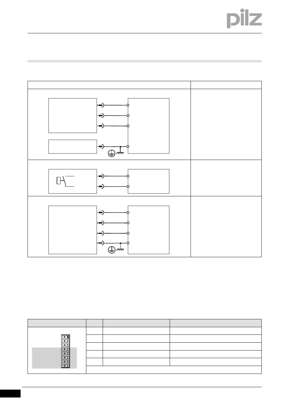
][Verdr_AI_protego_D_48_72
Connection
Output circuit
Digital output
24 VDC
Referenced to earth: Always con-
nect DGND (X3B/16) to I/O-GND
on the control system
Pin 6 and 7 must be configured as
a digital output in the commission-
ing software
Relay contact for operational read-
iness, servo amplifier
24 VDC
Referenced to earth: Always con-
nect DGND (X4/3) to I/O-GND on
the control system
Connector pin assignment
Connector X3B
Pin
Designation
Description
9
ANALOG-IN1-
Analogue input 1-
10
ANALOG-IN1+
Analogue input 1+
11
ANALOG-IN2-
Analogue input 2-
12
ANALOG-IN2+
Analogue input 2+
13
AGND
Reference earth for analogue inputs
DI 2
6
7
8
DGND
PMCprotego
24 V
I/O-GND
X3A
DIGITAL-INOUT1
DIGITAL-INOUT2
X3B
16
DI 1
24 V
I 2
14
15
PMCprotego
X3B
BTB/RTO
I 1
BTB/RTO
DI 2
8
6
1
DGND
PMCprotego
24 V
I/O-GND
X4
STO1-STATUS
3
DI 1
+24 V
STO2-STATUS
X3B
9
10
12
13
14
15
16
11
DGND
BTB/RTO
BTB/RTO
ANALOG-IN 2+
ANALOG-IN 2-
ANALOG-IN 1+
ANALOG-IN 1-
AGND