3 analogue inputs and outputs, 6wiring, 8 expansion cards – Pilz PMCprotego D.72/000/0/0/2/208-480VAC User Manual
Page 172
6.8
Expansion cards
6
Wiring
Pilz GmbH & Co. KG, Felix-Wankel-Straße 2, 73760 Ostfildern, Germany
Telephone: +49 711 3409-0, Telefax: +49 711 3409-133, E-Mail: [email protected]
6-64
6.8.3.3
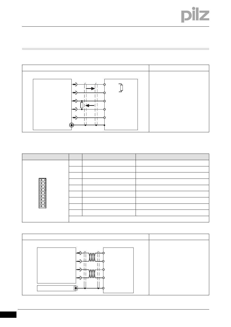
Analogue inputs and outputs
Analogue inputs and outputs
6-
][Verdr_Erw_POS_I/O_AiO_protego_D
Connection
Output circuit
Output of SSI signals
Shield connection in the connector
Always connect GND to the earth on
the control system
Select RT in accordance with the ca-
ble impedance, typically 150
Ω
Connector X3C
Pin
Designation
Description
17
ANALOG-OUT1
Analogue output 1
18
AGND
Reference earth for analogue output 1
19
ANALOG-OUT2
Analogue output 2
20
AGND
Reference earth for analogue output 2
21
ANALOG-IN3-
Analogue input 3-
22
ANALOG-IN3+
Analogue input 3+
23
AGND
Reference earth for analogue inputs
24
ANALOG-IN4-
Analogue input 4-
24
ANALOG-IN4+
Analogue input 4+
Connection
Output circuit
Analogue output
- Signal range –10 ... +10 V
- Referenced to earth: Always con-
nect AGND (X3B/13) to PLC-GND on
the control system
- Twisted pair, shielded
- Shield connection on the front plate
6
7
4
Servo Drive
X5
PLC
5
CLOCK
CLOCK\
DATA
DATA\
GND
1
GND
CLOCK
CLOCK\
DATA
DATA\
RT
RT
X3C
17
18
19
20
21
22
23
24
25
PLC-GND
17
ANALOG-OUT1
18
19
20
PMCprotego
AI 1
+/- 10 V
AI 2
PLC-GND
+/- 10 V
GND
X3C
Shield
AGND
AGND
ANALOG-OUT2
PLC