13 encoder emulation, 6wiring, 7 control element – Pilz PMCprotego D.72/000/0/0/2/208-480VAC User Manual
Page 158
6.7
Control element
6
Wiring
Pilz GmbH & Co. KG, Felix-Wankel-Straße 2, 73760 Ostfildern, Germany
Telephone: +49 711 3409-0, Telefax: +49 711 3409-133, E-Mail: [email protected]
6-50
Master-Slave mode
6.7.5.13
Encoder emulation
Encoder emulation
6-
][Verdr_Emulation_ROD_X1
Output of incremental encoder signals
Connector pin assignment
Connector X1
Pin
Designation
Description
2
0 V
Supply voltage 0 V
5
A
Channel A
8
B
Channel B
13
A\
Channel A inverted
15
B\
Channel B inverted
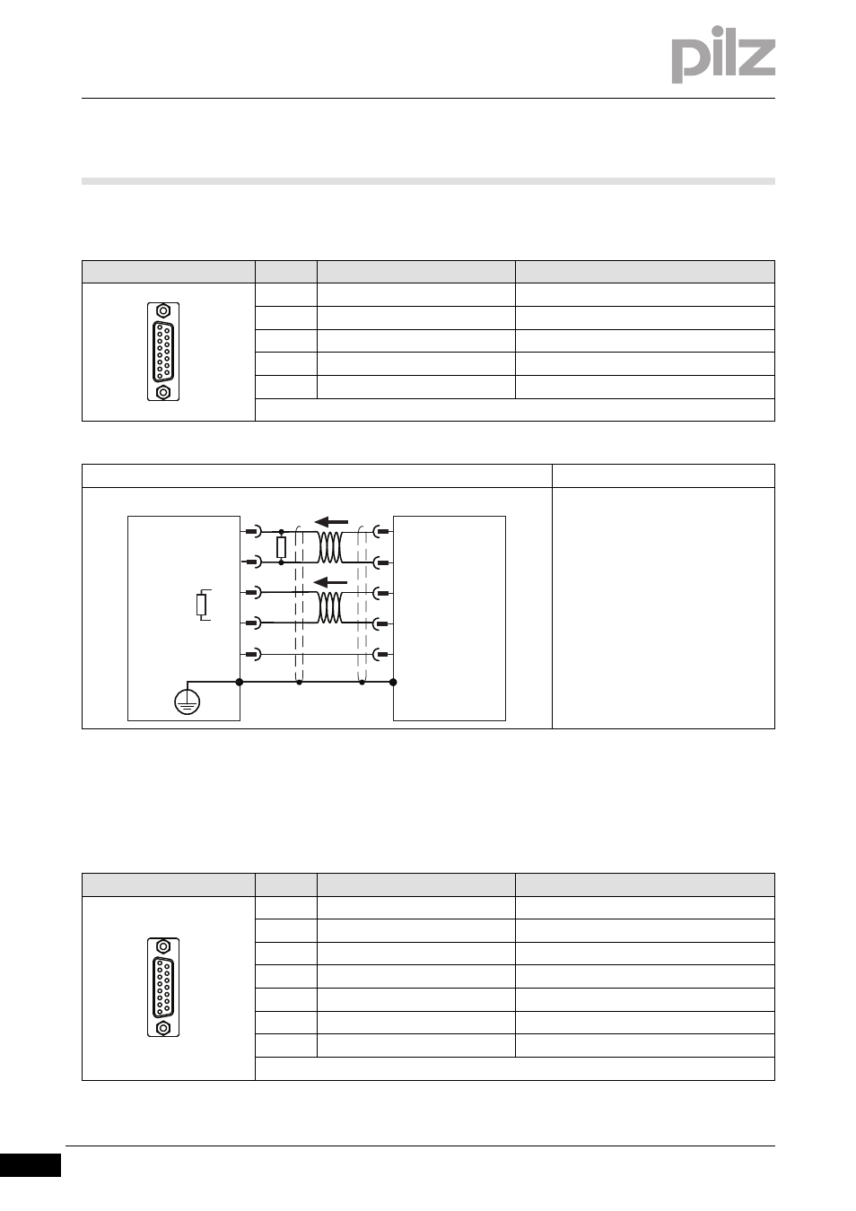
Connection
input circuit
Pulse/direction encoder 5 V
Twisted pair, shielded
Terminating resistor R
T
= 150 Ohm
(RS 485-compatible)
Connector pin assignment
Connector X1
Pin
Designation
Description
2
GND
Earth
3
NI
Zero pulse
5
B
Channel B
8
A
Channel A
11
NI\
Zero impulse inverted
13
B\
Channel B inverted
15
A\
Channel A inverted
1
8
9
15
8
15
13
PMCprotego Slave
X1
5
2
PMCprotego Master
0V
B
B\
A
A\
GND
RT
X1
B
B\
A
A\
8
15
13
5
2
1
8
9
15