6 connection example for sto, single-channel, 7 connection example for sto, dual-channel, 4function description – Pilz PMCprotego D.72/000/0/0/2/208-480VAC User Manual
Page 56: 3 control element
4.3
Control element
4
Function Description
Pilz GmbH & Co. KG, Felix-Wankel-Straße 2, 73760 Ostfildern, Germany
Telephone: +49 711 3409-0, Telefax: +49 711 3409-133, E-Mail: [email protected]
4-22
4.3.3.6
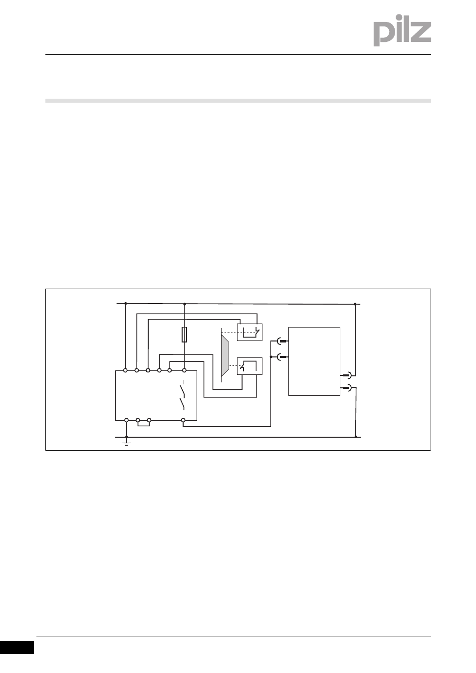
Connection example for STO, single-channel
Connection example for STO, single-channel
4-
][Funktion_STO_Beispiel_einkanalig_1
The following circuit example illustrates single-channel activation of the
safety function STO.
The drives are switched via a safety gate.
Safety gates S1/S2 are monitored by a safety relay PNOZ s3.
Shorts across contacts are detected.
The safety relay is wired for an automatic reset.
The safety function STO complies with PL d (Cat. 2) of EN ISO 13849-
1 and SIL CL 2 of EN/IEC 62061.
The relays' wiring must comply with the category or performance level
required for the application. Further information on the safety relays is
available from Pilz.
][Funktion_STO_Beispiel_einkanalig_2_D48
Fig. 4-7:
STO, single-channel with safety relay PNOZ s3
4.3.3.7
Connection example for STO, dual-channel
Connection example for STO, dual-channel
4-
][Funktion_STO_Beispiel_zweikanalig_D48
The following circuit example illustrates dual-channel activation of the
safety function STO.
Activation of the inputs STO1-ENABLE and STO2-ENABLE is dual-
channel, via the semiconductor outputs from a safety control system
PNOZ mm0p.
The status of the pulse disabler is tested periodically by evaluating the
two feedback signals STO1-STATUS and STO2-STATUS from the
safety control system.
PNOZ s3
A1 S11
STO1-ENABLE
STO2-ENABLE
S12 S21 S22 23
24
S12 S34
A2
X4
24V
0V
24 V
0 V
S1
S2
7
5
2
4
PMCprotego D