2 power leds – BECKHOFF EP9214-0023 User Manual
Page 19
Mounting and cabling
Contact
Voltage
1
GND Up
2
GND Us
3
FE (Functional earth), (as well as contact at central mounting holes)
4
Control voltage Us, +24 V
DC
5
Peripheral voltage Up, +24 V
DC
Attention
Do not confuse the power output with the EtherCAT connection!
Never connect the power cables (M8, 24 VDC) to the green-marked EtherCAT sockets of
the EtherCAT Box Modules. This can cause the destruction of the modules!
Control voltage Us: 24V
DC
The fieldbus and the processor logic are supplied from the 24 V
DC
control voltage Us. The control voltage is
electrically isolated from the fieldbus circuitry.
Peripheral voltage Up: 24V
DC
The peripheral voltage Up is monitored and fed to the power outputs, but is not used in the EP9214.
Redirection of the supply voltages
The power connections Power In and Power Out are bridged in the module. Hence, the supply voltages Us
and Up can be passed from EtherCAT Box to EtherCAT Box in a simple manner.
Attention
Observe the maximum current of the 7/8" plug connectors!
Also ensure when relaying the supply voltages Us and Up onward that the maximum per-
missible current of 16 A / 40 °C for each 7/8" plug connector is not exceeded!
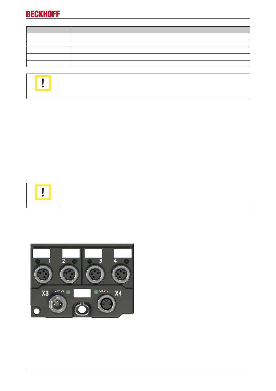
3.3.2
Power LEDs
Status-LEDs for the power supply
EP9214-0023 and EP9224-0023
19
Version 2.0.0