Pin assignment – BECKHOFF EP9214-0023 User Manual
Page 24
Advertising
Mounting and cabling
Fig. 20: M8 sockets
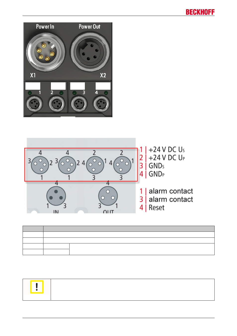
Pin assignment
Fig. 21: Pin assignment of the M8 sockets
Contact
Voltage
1
Control voltage Us, +24 V
DC
2
Peripheral voltage Up, +24 V
DC
3
GNDs*
*) can be internally connected to one another depending on the connected
module: see individual module descriptions
4
GNDp*
The contacts of the M8 plug connectors can conduct a maximum current of 4 A.
A LED indicates the status of the power outputs.
Attention
Do not confuse the power outputs with the EtherCAT connection
Never connect the power cables (M8, 24 V
DC
) to the green-marked EtherCAT sockets of the
EtherCAT Box Modules. This can cause the destruction of the modules!
EP9214-0023 and EP9224-0023
24
Version 2.0.0
Advertising
This manual is related to the following products: