4 remote control, 3 description of clo-10 features, 1 front panel – Comtech EF Data CLO-10 User Manual
Page 29: 2 rear panel, 4 major assemblies
CLO-10 Link Optimizer
Revision 1
Introduction
MN/CLO-10.IOM
1.2.4 Remote Control
The operator may configure and monitor the modem from the front panel, or through the remote
M&C port. M&C is via RS-232, RS-485 (2/4 wire) or 10/100 BaseT Ethernet.
1.3
Description of CLO-10 Features
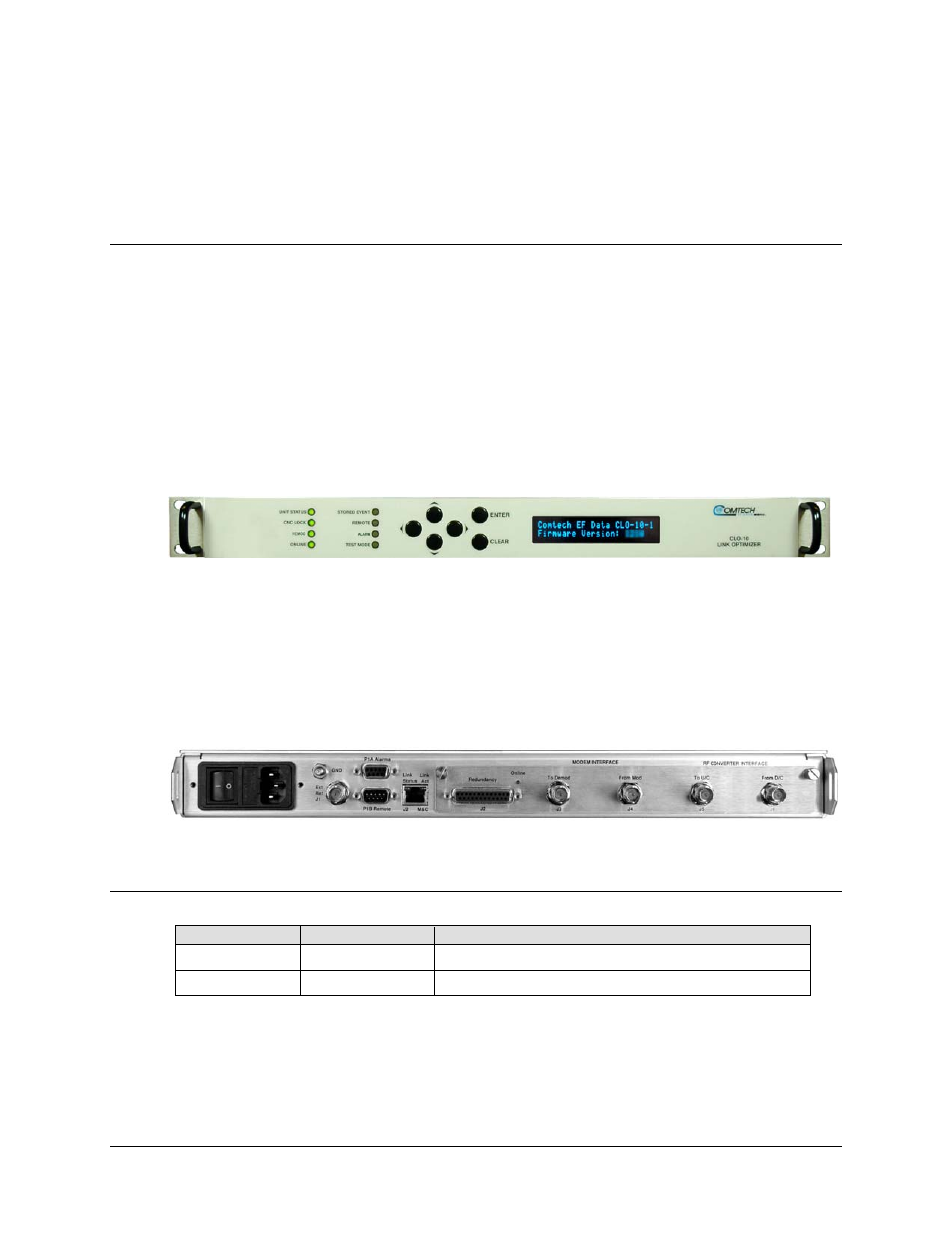
1.3.1 Front Panel
The CLO-10 is constructed as a 1RU-high, rack-mounting chassis that can be freestanding if desired.
It is provided with rack handles at the front for easy removal from and placement into a rack.
Figure 1-2 shows the CLO-10 front panel. The front panel features a Vacuum Fluorescent Display
(VFD), six-button keypad, and eight LED indicators. The user enters data via the keypad, and
messages are displayed on the VFD. The LEDs indicate, in a summary fashion, the status of the unit.
See
Chapter 6. Front Panel Operation
for detailed information pertaining to this functionality.
Figure 1-2. CLO-10 Front Panel
1.3.2 Rear Panel
Figure 1-3 shows the rear panel of the standard CLO-10-1 chassis configuration. Refer to
Chapter 3. REAR PANEL CONNECTORS
for detailed information about these connectors and
their functionality.
Figure 1-3. CLO-10 Rear Panel (CLO-10-1 shown)
1.4
Major Assemblies
Unit
Part No.
Description
CLO-10-1 PL/12833-1 Input
Output Module (IOM)
CLO-10-2 PL/12834-1 Input
Output Switch Module (IOSM) – 1:N
1–3