2 external reference connector, j1 (bnc-f), 3 alarms connector, p1a (db-9f), 4 remote control interface connector, p1b (db-9m) – Comtech EF Data CLO-10 User Manual
Page 44
CLO-10 Link Optimizer
Revision 1
Rear Panel Connectors
MN/CLO-10.IOM
3.2
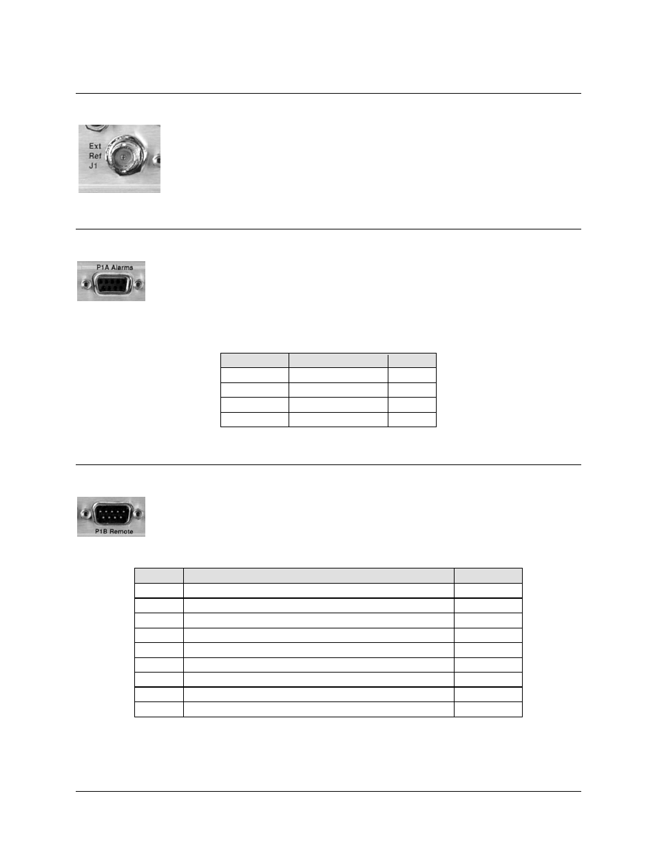
External Reference Connector, J1 (BNC-F)
The J1 External Reference Input is used to supply a master
reference to entire chassis. Use of an external reference is not
required. The input/output signal supplied here by the user is used for
phase-locking the internal 10MHz reference oscillator, and can be 1,
2, 5, or 10 MHz. The impedance is matched for 50/75
Ω, and requires
a level in the range 0.5V-4.0Vpp square or sine wave.
3.3
Alarms Connector, P1A (DB-9F)
The P1A Alarms connector is a Type 'D' 9-pin female connector (DB-9F), providing
the user with access to the Form-C relay contacts that indicate the fault status of the
unit. P1A is typically connected to an external fault monitoring system, often found in
satellite earth stations.
Table 3-2. Alarm Interface Connector Pin Assignments
Pin #
Signal Function
Name
8
Unit is faulted
NO
3
Unit is not faulted
NC
7
Unit Alarm common
COM
1,2,4,5,6,9 NOT
USED
--
3.4
Remote Control Interface Connector, P1B (DB-9M)
The P1B Remote Control connector is a Type ‘D’ 9-pin male connector (DB-9M), providing
the user with access to both EIA-232 and EIA-485 remote control ports of the modem.
Table 3-3. Remote Control Interface Connector Pin Assignments
Pin #
Description
Direction
1 Ground
2
EIA-232 Transmit Data
Out
3
EIA-232 Receive Data
In
4 Reserved—NO
CONNECT
5 Ground
6
EIA-485 Receive Data B *
In
7
EIA-485 Receive Data A *
In
8
EIA-485 Transmit Data B
Out
9
EIA-485 Transmit Data A
Out
*NOTE: Use for 2-wire EIA-485 operation.
3–2