6 iom/iosm connectors (bnc-f) – Comtech EF Data CLO-10 User Manual
Page 46
CLO-10 Link Optimizer
Revision 1
Rear Panel Connectors
MN/CLO-10.IOM
3.6
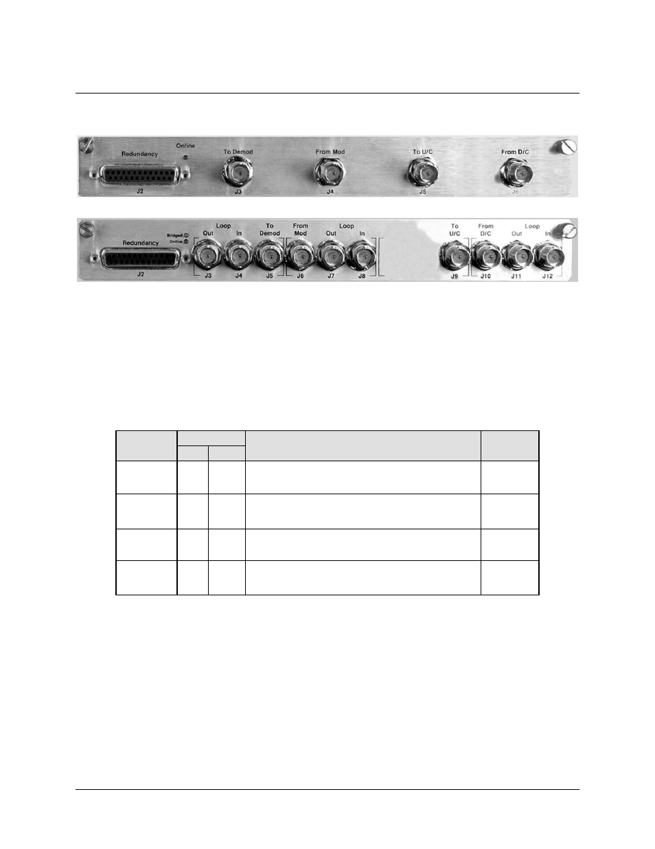
IOM/IOSM Connectors (BNC-F)
The CLO-10 may be used in Standalone configuration with either the Input/Output Module (IOM) or
Input/Output Switch Module (IOSM) installed. Table 3-5 defines use of the BNC connectors (in
Standalone and in Daisy Chain Redundancy configurations) for both modules.
Note that the J2 DB-25F Redundancy connector is not used in a Standalone configuration. For detailed
information pertaining to the IOM/IOSM connectors used in Daisy Chain Redundancy configuration,
refer to Appendix A. REDUNDANCY SYSTEM OPERATION.
Table 3-5. CLO-10 IOM BNC Connectors Reference
BNC
Connector
Ref. Des.
Description / Function
Direction
IOM
IOSM
To Demod
J3
J5
Output to Demod – signal from the downconverter
with the near-end carrier suppressed.
Out
From Mod
J4
J6
Input from near-end Modulator – used as
reference copy for cancellation processing.
In
To U/C
J5
J9
Output to Upconverter – same signal as J4/J6
with up to 5 dB ±0.2 dB loss.
Out
From D/C
J6
J10
Composite signal from Downconverter – far-end
carrier signal summed with the near-end carrier.
In
3–4