A.3.2.2 iom / iosm bnc connectors – Comtech EF Data CLO-10 User Manual
Page 91
CLO-10 Link Optimizer
Revision 1
Redundant System Operation
MN/CLO-10.IOM
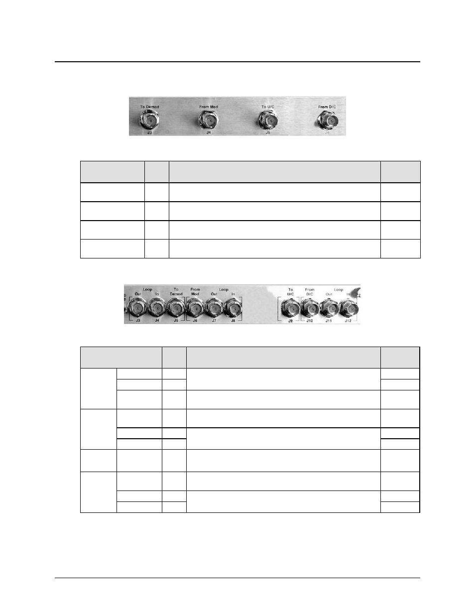
A.3.2.2 IOM / IOSM BNC Connectors
Table A-1. IOM (CEFD P/N PL/12833-1) BNC Connectors Reference
BNC Connector
Ref.
Des.
Description / Function
Direction
To Demod
J3
Output to Demod – signal from the downconverter with the
near-end carrier suppressed.
Out
From Mod
J4
Input from near-end modulator – used as reference copy for
cancellation processing.
In
To U/C
J5
Output to Upconverter – same signal as J4 with up to 1.5 dB
loss.
Out
From D/C
J6
Composite signal from Downconverter – far-end carrier
signal summed with the near-end carrier.
In
Table A-2. IOSM (CEFD P/N PL/12834-1) BNC Connectors Reference
BNC Connector
Ref.
Des.
Description / Function
Direction
Demod
Group
Loop Out
J3
Connects the previous Traffic Unit into the Daisy Chain
system.
Out
Loop In
J4
In
To Demod
J5
Output to Demod – signal from the downconverter with
the near-end carrier suppressed.
Out
Mod
Group
From Mod
J6
Input from near-end modulator – used as reference copy
for cancellation processing.
In
Loop Out
J7
Connects the previous Traffic Unit into the Daisy Chain
system.
Out
Loop In
J8
In
U/C To
U/C J9
Output to Upconverter – same signal as J6 with up to 5
dB loss
Out
D/C
Group
From D/C
J10
Composite signal from Downconverter – far-end carrier
signal summed with the near-end carrier.
In
Loop Out
J11
Connects the previous Traffic Unit into the Daisy Chain
system.
Out
Loop In
J12
In
A–7