Chapter 3. rear panel connectors, 1 connector overview – Comtech EF Data CLO-10 User Manual
Page 43
Chapter 3. REAR PANEL
CONNECTORS
3.1
Connector Overview
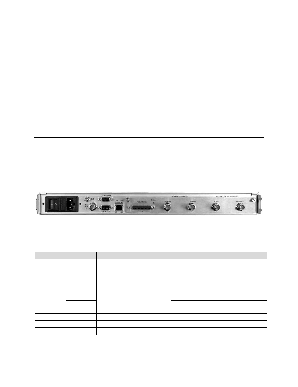
The connectors located on the CLO-10 rear panel (Figure 3-1) provide all necessary external
connections between the modem and other equipment.
Table 3-1 summarizes these connections and identifies the chapter sections providing more
detailed information.
Figure 3-1. CLO-10 Rear Panel (CLO-10-1 Shown)
Table 3-1. External Connections
Name
Sect
Connector Type
Function
Ext Ref
3.2
BNC (female)
External 1,5, 10 MHz Reference input
Alarms
3.3
9-Pin Type ‘D’ (female)
Form C Unit Alarm
Remote
3.4
9-Pin Type ‘D’ (male)
Serial Remote Control Interface
M&C
3.5
RJ-45
10/100 Ethernet M&C
IOM / IOSM
Interface
To Demod
3.6 BNC
(female)
Output to Demod
From Mod
Input from Uplink Modulator
To U/C
Output to Upconverter
From D/C
Input from Downconverter
(AC Plug)
3.7
IEC Modem
Power
(DC Connector – not shown)
3.8
Terminal Block
Modem Power
GND
3.9
#10-32 Stud
Grounding
3–1